
(H)EV Main INVERTERS Configuration and Technological Trends
High-efficiency motor control system supporting next-generation electric powertrains
1. What is an (H)EV main INVERTERS?
The main INVERTERS is a power electronics system that converts the direct current (DC) power from the high-voltage battery into three-phase alternating current (AC) power to control the drive motor. It is the core unit responsible for the operation of HEVs, PHEVs, and BEVs. It is responsible not only for torque control in response to accelerator operation but also for power generation control through regenerative braking, and greatly affects the overall energy efficiency of the vehicle.
In recent years, the adoption of highly efficient SiC power devices and the raising of voltage to 800V have been rapidly progressing in order to extend driving range and support fast charging.
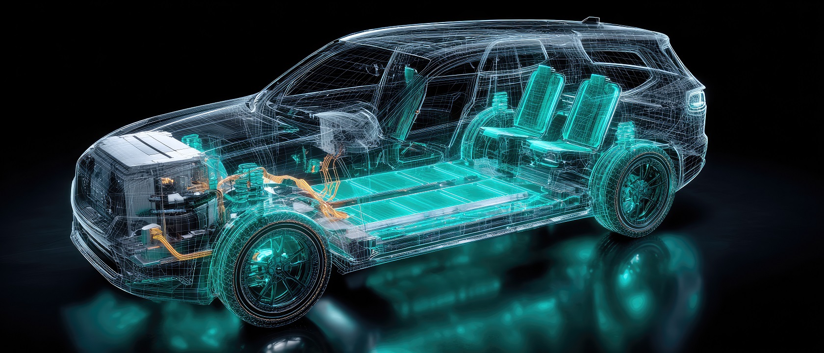
2. System Configuration
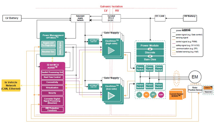
The main INVERTERS primarily consists of a high-voltage battery, DC link CAPACITORS, power module (IGBTS /SiC MOS FETS), GATE DRIVER, current and ELECTRIC VOLTAGE SENSORS, and a control MCU.
The following is a block diagram showing the main components. The MCU controls SWITCHES while constantly monitoring the current and voltage to optimize the motor's rotation speed, torque, and efficiency.
3. Flow of Operation
When the driver presses the accelerator, a torque request is sent from the vehicle control ECU to INVERTERS control ECU (MCU). The MCU monitors the motor's rotational position and current value in real time and calculates the amount of power that should be supplied.
Based on the calculation results, the power module (IGBTS or SiC MOS FETS) is SWITCHES at high speed from several kHz to tens of kHz via GATE DRIVER, converting the DC power from the battery into three-phase AC power and supplying it to the motor.
On the other hand, during deceleration, the motor acts as a generator, and the generated electricity is returned to the battery via INVERTERS in a regenerative braking system. This recovers braking energy and contributes to improved energy efficiency and fuel economy.
4. Main design challenges
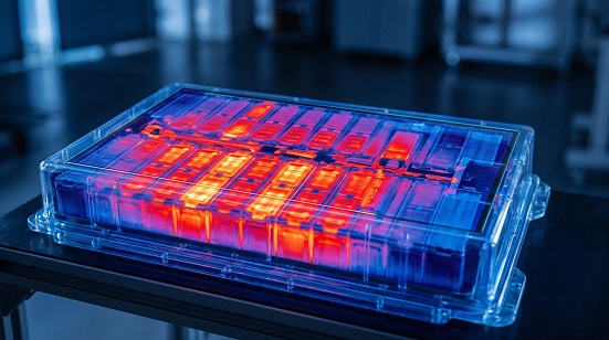
Main INVERTERS design requires balancing multiple requirements at a high level. Firstly, high efficiency is essential. Reducing SWITCHES losses and conduction losses is key to improving driving range. Secondly, heat generation and dissipation are crucial. A cooling design that efficiently dissipates the heat generated by increased power output is indispensable and directly impacts the reliability and lifespan of the power module.
Furthermore, noise and EMC countermeasures resulting from high-speed SWITCHES, functional safety design based on ISO 26262, and miniaturization and high power density within limited mounting space are also important challenges.
5. Technology Trends
Main INVERTERS have evolved significantly in recent years. The most notable advancement is the shift to SiC (silicon crystalline silicon), where replacing conventional IGBTS with SiC MOS FETS simultaneously achieves higher efficiency and higher power density. Furthermore, the adoption of 800V architectures is expanding to improve rapid charging performance and reduce wiring losses.
In addition, highly integrated systems that combine power modules, GATE DRIVER, and sensors, as well as advanced motor control using software such as FOC (vector control), are becoming commonplace.

6. Design Approach
Achieving high-performance INVERTERS requires optimization of the entire system, not just individual devices. The selection of power devices (IGBTS /SiC), optimization of gate drive, and ensuring current sensing accuracy significantly impact quality.
Especially when using SiC MOS FETS, board layout, gate control design, and noise countermeasures become even more important in order to maximize the benefits of high-speed SWITCHES.
By taking a comprehensive approach that includes heat dissipation design, EMC countermeasures, and safety design in accordance with ASIL standards, we achieve highly efficient and reliable systems.
7. The value that Infineon can offer
INVERTERS for EVs/HEVs require a high level of efficiency, reliability, and functional safety. This necessitates optimal power devices, high-precision sensing, and automotive-grade control solutions.
Infineon offers a wide range of solutions, from power modules such as CoolSiC™ MOS FETS and HybridPACK™, to AURIX™ MCUs, GATE DRIVER with diagnostic capabilities, and POWER SUPPLIES ICs.
This makes it easier to achieve values such as increased efficiency, miniaturization, increased reliability, and functional safety compliance across the entire system.
8. Related Products
This page focuses on the main INVERTERS application itself, but in actual design, the selection of devices such as SiC MOS FETS, power modules, GATE DRIVER, automotive MCUs, and POWER SUPPLIES ICs is also important. For related products tailored to your application and requirements, please see the product introduction page via the link below.
-
MOS FETS: OptiMOS™ and CoolMOS™ achieve high efficiency in power conversion.
-
Gate Driver: GATE DRIVER with high voltage resistance and high insulation capabilities, ensuring both safety and performance.
-
Automotive Microcontrollers: Supporting Next-Generation Automotive System Development with AURIX™ and TRAVEO™
9. FAQ
The configuration varies depending on the OEM and Tier 1 supplier. Generally, the MG-ECU refers to the motor control calculation unit, while the main INVERTERS often refers to the entire system including the power conversion unit (power module, etc.).
This is because it significantly reduces SWITCHES losses compared to IGBTS, contributing to improved range through increased efficiency and miniaturization.
Because the current can be reduced even with the same output, wiring losses and heat generation can be suppressed, contributing to improved rapid charging performance.