When selecting sensors for product development, multiple requirements must be met simultaneously, such as accuracy, power consumption, size, and environmental resistance. In recent years, the number of applications requiring energy-efficient operation and locations with large environmental fluctuations has increased, and there are many cases where conventional methods are unable to meet all of these requirements.
60GHz millimeter-wave sensors are attracting attention as a method that can withstand environmental conditions such as darkness and bad weather, and can be used for a wide range of applications from distance measurement to minute motion detection. However, there are multiple detection methods for millimeter-wave sensors, and selecting the wrong method can lead to issues with power consumption and operation.
This article focuses on the PCR (Pulsed Coherent Radar) method adopted in the 60 GHz millimeter wave sensor IC "A121" provided by Acconeer AB (hereinafter referred to as Acconeer), and explains its technical features and selection points through a comparison with other methods.
Why choose mmWave sensors?
Each of the sensor methods that have been widely used up until now has its own limitations. Infrared (IR) is easily affected by the lighting environment and temperature changes, cameras have issues with privacy considerations and the image processing load, ultrasonic waves are easily affected by wind and temperature changes, and capacitance is vulnerable to water and humidity.
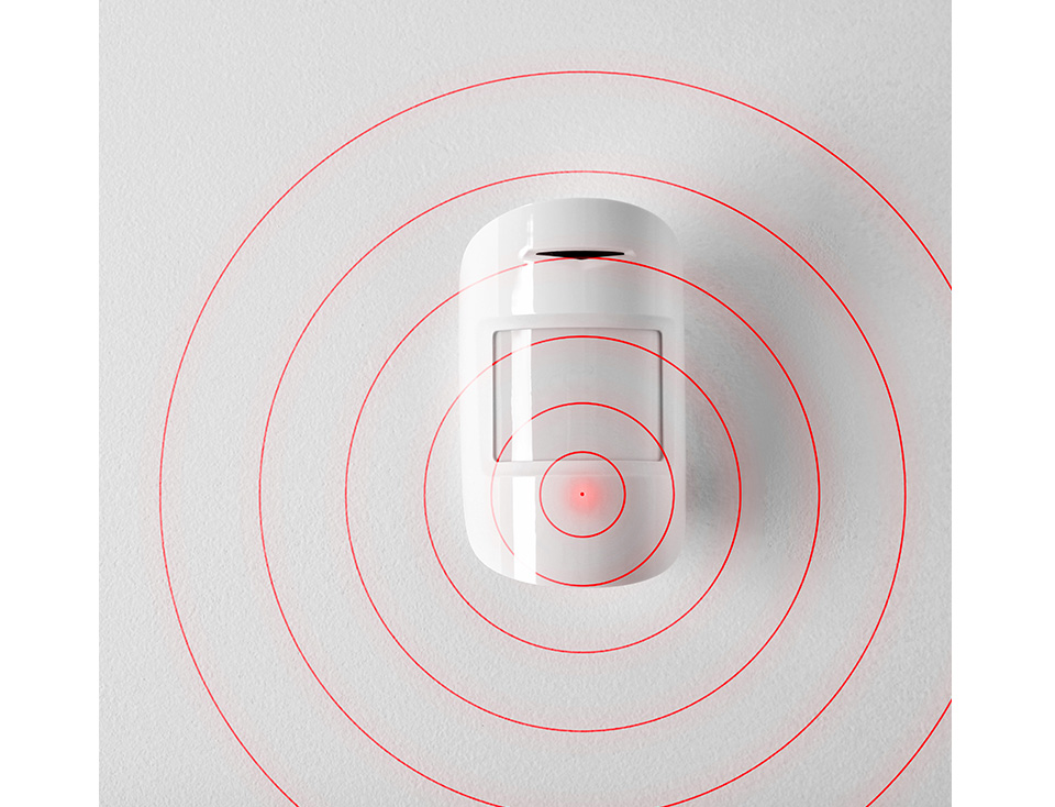
On the other hand, millimeter-wave sensors use radio waves, making them less susceptible to environmental changes such as darkness, backlight, smoke, and bad weather, enabling stable detection. Furthermore, by taking advantage of their ability to penetrate non-metallic materials, millimeter-wave sensors can achieve presence detection, distance measurement, and minute movements with a single sensor.
Due to these characteristics, mmWave sensors are increasingly being adopted as an alternative to IR and ultrasonic, and as part of hybrid configurations that integrate multiple methods.

millimeter wave sensor
INFRARED LIGHT PHOTOSENSORS

camera sensor
Figure 1: Various sensor methods
Table 1 compares the major sensor methods based on evaluation criteria such as "environmental resistance," "measurement accuracy," "operating principle," and "features and challenges."
Table 1 Comparison of major sensor methods
| Item | millimeter wave | Infrared (IR) | capacitance | Ultrasound | camera | magnetic |
|---|---|---|---|---|---|---|
| Operating principle | Analyzes the reflection time and phase difference of radio waves | Detects the intensity of reflected and emitted light | Detects changes in capacitance between electrodes | Measures the reflection time of ultrasonic waves | Acquire and analyze images | Detects changes in magnetic fields |
| Main uses | Distance measurement Presence Detection Speed Detection Minute motion detection | Object detection Temperature detection Motion detection | Proximity Detection Contact detection Liquid level detection | Distance measurement Presence Detection | object recognition motion recognition | Metal Position Detection |
| Measurement accuracy | ◎ (mm class) | ○~◎ (depending on the material of the object) | ◎ (mm class) | ○(cm class) | ◎ (Depends on analysis algorithm) | ◎ |
| environmental resistance | ◎ | Yes (affected by lighting and temperature) | ◎ (Weak against moisture) | △ (largely affected by wind and temperature) | △ (weak in dark places and bad weather) | ○ |
| Measurement distance | Short to long distance | short distance | short distance | short to medium distance | Medium to long distance | short distance |
| Features | - Resistant to bad weather -Can penetrate non-metallic materials ・Slight motion detection possible | ・Low cost ・Low power consumption | - High sensitivity to minute changes | -Easy to configure ・Low cost | ・A lot of information can be obtained (The AI processing at the later stage is important) | - Resistant to dirt and water |
| assignment | ・Low-reflectivity materials are difficult to detect | ・Window material is required | - Easily affected by temperature and humidity | ・Highly dependent on the environment | ・High processing load ・Privacy considerations are necessary | ・Cannot detect anything other than metal |
mmWave sensors are not only less susceptible to environmental changes such as darkness, backlight, and bad weather, but also offer high accuracy in distance measurement and minute motion detection. These characteristics make it easy to understand why mmWave is being widely adopted in modern applications where a single method is no longer sufficient.
While it is easy to understand that millimeter wave sensors are a promising option, we need to take a step further to determine which detection method to choose depending on the application.
In the next chapter, we will summarize conventional millimeter wave sensor technology and Acconeer's proprietary PCR method.
Characteristics and limitations of typical detection methods in millimeter-wave sensors
As millimeter wave sensors are gaining attention, it is important to understand the differences in the detection methods used internally in order to extract the performance appropriate for the application.
There are several typical detection methods for mmWave sensors, each with different strengths and limitations.
-
FMCW (Frequency Modulated Continuous Wave) method
This method transmits a continuous wave with a continuously changing frequency and analyzes the reflected wave, enabling simultaneous measurement of distance and speed with high accuracy. It is widely used in applications such as automotive radar, and is characterized by the large amount of information it can obtain. However, signal processing can be complex, power consumption is relatively high, and design challenges include issues with interference when multiple units are operating simultaneously.

Output radio wave image

Application example: Collision prevention
Figure 2. FMCW system usage image
-
Pulse method
This method transmits a short pulse signal and measures distance from the reflection time. It is suitable for long-distance measurement and detecting fast-moving objects, and has the advantage of easily separating transmission and reception in time. However, because distance resolution depends on the pulse width, high-speed signal processing and hardware design are required to achieve high accuracy. Also, depending on the distance requirement, transmission energy may increase, which may result in higher average power consumption.

Output radio wave image

Application example: High-speed moving object detection
Figure 3: Pulse method usage image
-
CW (Continuous Wave) method
This method transmits a continuous wave of a fixed frequency and mainly uses the Doppler effect to detect speed and movement. The circuit configuration is relatively simple, making it suitable for applications specialized in speed detection. However, it has limitations such as an inability to measure distance and difficulty in separating multiple objects.

Output radio wave image

Application example: Speed detection
Figure 4. CW method usage image
As such, while all conventional detection methods are effective for specific applications, there are trade-offs in terms of power consumption, complexity of signal processing, operation of multiple units, and high-precision detection at short distances.
In particular, for short- to medium-range applications such as human detection and presence detection, there are emerging demands for "reducing power consumption while maintaining high accuracy" and "placing multiple sensors close together."
With this background in mind, the next chapter will explain the PCR method that was developed to address these issues.
What is PCR? An approach that combines power saving and high accuracy
The PCR (Pulsed Coherent Radar) method is a detection method designed to achieve both power saving and high accuracy, taking into account the characteristics and issues of these conventional methods. Developed independently by Acconeer, it combines the advantages of both pulsed and coherent methods.
The PCR method periodically transmits a series of short continuous wave pulses and analyzes the reflected waves. Because continuous transmission is not performed, the transmission duty is lower than with the FMCW method, which is advantageous in that it reduces average power consumption. At the same time, by using the phase information of the reflected waves, high resolution can be achieved for distance and minute movements.

Figure 5. Image of PCR output radio wave
The main features of the PCR method can be summarized as follows:
-
low power consumption
By minimizing transmission time, average power consumption can be reduced. -
High precision
High time resolution and phase analysis in the 60 GHz band achieves millimeter-level distance resolution. -
Minute motion detection
Phase difference analysis makes it possible to detect minute movements such as breathing and slight movements. -
Simultaneous operation of multiple machines
Because the transmission duty is low and interference is unlikely to occur, stable operation can be expected even in environments where multiple sensors are located close to each other.
These features make the PCR method suitable for short- to medium-range applications where high accuracy must be maintained while reducing power consumption and operational constraints.
Table 2 compares PCR with FMCW, pulsed, and CW systems from the perspectives of "operating principle," "areas of expertise," "power consumption," and "multi-unit operation." By looking at the positioning of each system, it becomes easier to understand what applications PCR is designed for and what its advantages are compared to conventional systems.
Table 2 Comparison of millimeter wave sensor detection methods
| Item | PCR | FMCW | Pulse | CW |
|---|---|---|---|---|
| Operating principle | Transmits a short continuous wave pulse train and analyzes the time and phase of the reflected wave | Distance and speed are analyzed using continuous waves with continuously changing frequencies | Distance is measured from the reflection time of the pulse signal | Transmits a continuous wave of a fixed frequency and analyzes the Doppler component |
| Suitable uses | Short to medium distance human detection Presence Detection Minute motion detection Distance and speed measurement | Collision prevention Distance and speed measurement Human Presence Detection | Long-distance measurement High-speed moving object detection | Speed Detection Motion detection Respiration and heart rate measurement |
| Distance resolution | ◎ (mm class) | ◎ (high resolution) | ○ (Depends on pulse width) | △ |
| Speed measurement | ◎ | ◎ | ○ | ◎ |
| Average power consumption | ◎ | △ | ◎ (Good for long distance use) | ○ |
| Simultaneous operation of multiple machines | ◎ | △ (Difficult to distinguish between self and others) | △ (Interference due to synchronization loss) | △ |
| Main Features | - Low power consumption and high accuracy ・Slight motion detection possible ・Strong in multi-unit operation | -Highly accurate distance and speed measurement ・Lots of information | ・Strong against high-speed moving objects -Easy to separate transmission and reception | ・Simple circuit configuration - Specialized for speed detection |
| Design Challenges | ・Not suitable for long-distance positioning | ・Signal processing is complex - High power consumption ・Interference prevention measures are required | ・Distance accuracy is limited by the pulse width ・High-speed circuit design is required | ・Distance measurement not possible ・Difficult to separate multiple objects |
Acconeer A121 - 60GHz mmWave Sensor IC with PCR Technology

Figure 6 A121 (BGA with built-in ANTENNAS) Source: Acconeer
Acconeer's A121 is a 60 GHz millimeter-wave sensor IC based on the PCR method.
The A121's features can be summarized in three points: high accuracy and wide range measurement, low power consumption, and a small integrated package.
High accuracy and wide range measurement
The 60 GHz band improves time resolution, achieving millimeter-level distance accuracy. Furthermore, phase analysis enables the detection of minute relative displacements.
The profile setting allows you to adjust the pulse duration and shape, covering measurements from close range with high resolution up to approximately 23 m (depending on conditions).
low power consumption
Since the continuous transmission time is short and the non-transmission time is long, power consumption can be significantly reduced compared to continuous wave methods.
In addition, it has multiple power management modes that allow power consumption to be optimized according to measurement frequency.
Table 3 A121 power management modes
| Power Management Modes | Sensor Status | Current consumption (VDIG) | Recovery time |
|---|---|---|---|
| Ready | Measurement conditions | Large (58.1mA) | Short (0s) |
| Sleep | Simple sleep state | ||
| Deep Sleep | Sleep state | ||
| Hibernate | Hibernation | ||
| Off | Stopped state |
Small integrated package
The baseband processor, RF front-end, and ANTENNAS are integrated into a single package, eliminating the need for an external ANTENNAS design.
The package uses a small BGA form factor of 5.5 x 5.2 x 0.88 mm, making it easy to incorporate into products with strict housing constraints.
A121 evaluation board and software tools
This chapter is for those evaluating the A121 for the first time, and explains how to select an evaluation board and the basic operations of the software evaluation tool (Exploration Tool: AET).
How to choose an evaluation board
Acconeer offers several evaluation board options for evaluating the A121, depending on the application. It is important to select the appropriate configuration depending on the purpose of the evaluation and the development phase.
- XE121 Evaluation Board (A121)

Figure 7 XE121 Evaluation Board (A121) Source: Acconeer
The XE121 is an evaluation board equipped with one A121 sensor IC.
This board does not have an MCU, so it is used in combination with an external controller such as the XC120 (CONNECTORS board), Raspberry Pi, or STM32 Nucleo board.
When connecting to a PC, a USB connection is made via the XC120, and evaluation using AET is possible (AET is not supported when using Nucleo).
In addition, up to four XS121 satellite boards can be connected as an option, enabling evaluation of multiple sensor configurations.
The XE121 is a suitable configuration for those considering modularization in-house or centralized control of multiple sensors.

Figure 8 XE121 evaluation board combination. Source: Acconeer
- XE125 Evaluation Board (XM125 Module)
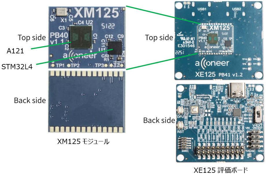
Figure 9 XM125 module and XE125 evaluation board. Source: Acconeer
The XM125 is a compact radar sensor module equipped with an A121 sensor and an STM32L4 microcontroller, developed for embedded products.
The XE125 is an evaluation board equipped with the XM125 module, and is designed for evaluation and prototyping.
Simply connect to a PC via USB and start evaluation using AET or the SDK provided by Acconeer.
Since no external controller is required, it is suitable for checking the basic characteristics of the A121 in a short time or for initial evaluation assuming module adoption.
- Evaluation board comparison and selection guidelines
The features of the XE121 and XE125 evaluation boards are summarized in Table 4.
The XE125 is suitable for short-term characteristic confirmation, while the XE121 is suitable for evaluation of in-house product integration or multi-sensor configurations.
Since the A121 itself is the same, there is no significant difference in the performance or applications that can be evaluated. It is best to select one based on how you want to build your evaluation environment and your degree of freedom in development.
Table 4. Features of the A121 evaluation boards XE121 and XE125
| Item | XE121 evaluation board | XE125 evaluation board |
|---|---|---|
| exterior |
 |
 |
| composition | A121 Sensor IC x 1 X'tal ×1 XS121 CONNECTORS x 4 | XM125 module (A121, STM32L4, X'tal installed) ×1 |
| Dimensions | 65.0×68.0 mm | 42.0×47.0 mm |
| controller | External CPU board required (XC120/Raspberry Pi/Nucleo) | No external CPU board required |
| Interface | SPI, USB (when connecting XC120) | USB, UART, I2C |
| Evaluation method | There are two ways to evaluate: 1. Evaluate by connecting via USB to a PC with AET installed (excluding Nucleo) 2. Implementing the SDK provided by Acconeer on the MCU and evaluating it Furthermore, since the sensors are the same, the applications and performance that can be evaluated are almost the same. | |
| Suitable uses | ・In-house modularization - Control multiple sensors collectively | ・Module adoption is required ・I want to start evaluation in a short time |
Software Exploration Tool

Figure 10 Exploration tool Source: Acconeer
Acconeer offers a software evaluation tool called the Exploration Tool (AET) to efficiently evaluate the operation and characteristics of the A121. The A121 can acquire a variety of information, including IQ data, reflection intensity, and distance profiles, and a major feature of the AET is that it visualizes this information in a GUI and allows parameters to be easily changed on the GUI. Since sensor settings and result confirmation can be performed in one stop, it can be used flexibly from initial evaluation to algorithm verification.
AET comes pre-loaded with several evaluation applications, allowing you to start evaluating immediately without writing any code.
Typical applications are as follows:
- Sparse IQ: Visualize raw IQ data for algorithm validation and micromotion analysis
- Distance detector: Measures distance based on reflection intensity profile
- Presence detector: Detects the presence of a target
- Speed detector: Detects speed from Doppler data
Other applications include respiration measurement, water level measurement, and vibration detection.
For example, the AET user interface in Sparse IQ mode is shown below.
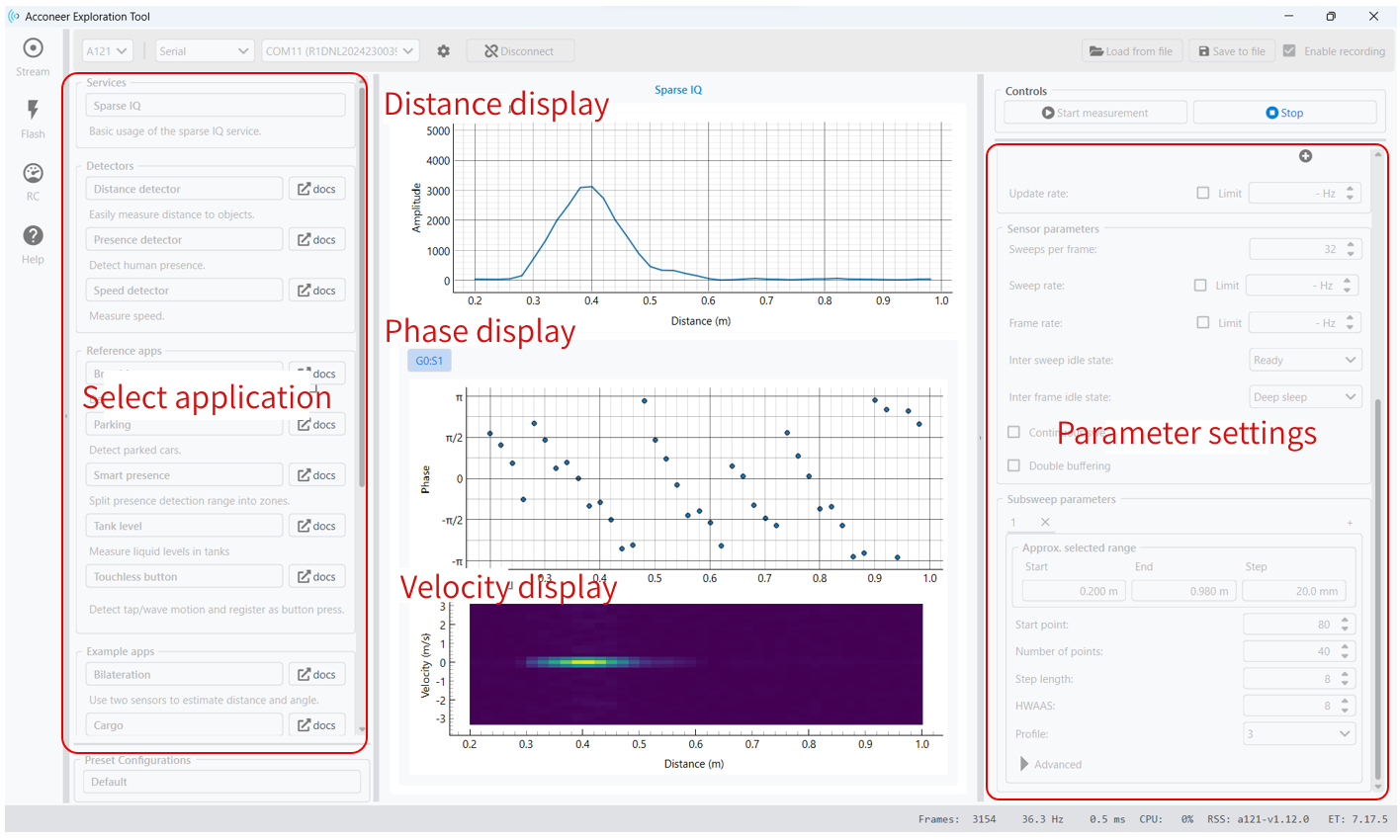
Figure 11. AET user interface in Sparse IQ mode. Source: Acconeer
Select the application on the left side of the screen and set the parameters on the right side of the screen.
The main parameters that can be set in Sparse IQ mode are:
- Start point: Measurement start distance (2.5 mm x set value)
- Number of points: Number of measurement points
- Step length: distance between points (2.5 mm x set value)
- HWAAS: Hardware averaging for S/N improvement
- Profile: Pulse duration and shape
By adjusting these parameters, the measurement distance range, resolution, and S/N ratio can be optimized.
The center of the screen shows the Sparse IQ measurement results, visualizing distance, phase, and speed information.
- Distance display: Determine the distance to the target from the peak position of the reflection intensity
- Phase display: Detects minute movements using time-varying phase
- Speed display: Analyzes Doppler information for each distance to visualize speed
This allows you to check the A121's distance measurement performance and ability to detect minute movements in real time.
Summary
This article focuses on the detection method of millimeter wave sensors and explains Acconeer's PCR method and the features of the A121.
The PCR method is effective for short- to medium-range applications when you want to simultaneously achieve low power consumption, high accuracy, and multi-unit operation.
If you are considering applications such as motion detection, presence detection, or minute motion detection, the A121 is a very compelling choice.
In the next issue, we will introduce each application of the Exploration tool and some specific examples of how the PCR method can be used.
Related Info
Related pages on the NEXTY special site
RF (Radio Frequency) Technology Column