

- Analog Devices, Inc.
- NEXT Mobility
1. Background
While automotive cameras traditionally had resolutions around 1 to 2 megapixels, recent rapid advancements in ADAS (Advanced Driver Assistance Systems) have created a demand for higher pixel counts in sensing cameras. Figure 1
GMSL from ADI (formerly MAXIM) is already widely used for high-speed video data transmission in vehicles.
While GMSL supported video up to 2 MP resolution, the newly released GMSL2 enables handling video data from higher-resolution cameras.
This page explains the features of ADI's (formerly MAXIM) next-generation GMSL, GMSL2.
2. MAX96717 CSI-2 to GMSL2 Serializer
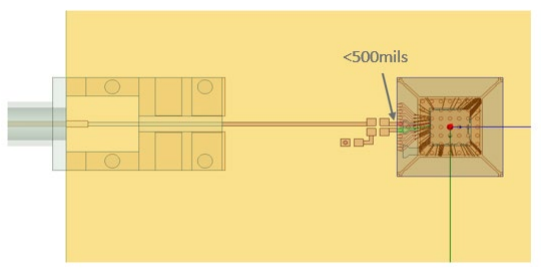
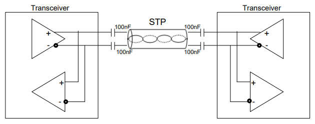
One key component is the MAX96717, a second-generation GMSL serializer capable of achieving communication speeds up to 6Gbps. It serially transmits data received via its MIPI CSI-2 (4-lane D-PHY) input over the GMSL line using either STP or COAX cable.
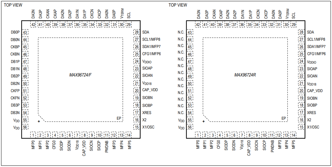
The device comes in a 5x5mm TQFN package (see left figure).
As an application example, four camera modules equipped with the MAX96717 can be combined with the MAX96724 Quad Port GMSL2 Deserializer. (see right figure)

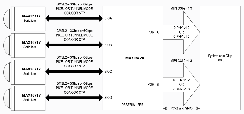
MAX96717 CSI-2 to GMSL2 Serializer Features
- Forward channel 3Gbps or 6Gbps, reverse channel 187.5Mbps
- 4-lane MIPI CSI-2 v1.3 input port
- MIPI D-PHY v1.2 receiver
- Automotive qualified, ASIL-B compliant
- I2C / UART, pass-through I2C/UART, SPI, GPIO, and register-programmable GPIO
- End-to-end data integrity via CRC (tunneling mode)
- Crystal-free operation using RoR (Reference over Reverse) clock
- 32-Pin (5mm x 5mm) TQFN Side-Wettable Package, 0.5mm pitch
MAX96724 Quad Tunneling GMSL2 / 1 to CSI-2 Deserializer Features
- Quad GMSL inputs, individually configurable
- Link rate: 6 / 3Gbps (GMSL2) and 3.12Gbps (GMSL1)
- Reverse link rate: 187.5Mbps / 1Mbps (GMSL2 / 1)
- Supports mixing GMSL2 / 1 pixel input and tunnel input
- 2x4 or 4x2 lane MIPI CSI-2 v1.3 output
- C-PHY v1.0 rated (5.7Gbps / lane)
- Supports DPHY v1.2 at 2.5Gbps / lane
- Automotive qualified, ASIL-B compliant (MAX96724 / F)
- I2C ports x 2: up to 1Mbps, configurable GPIO x 9
- Reference-over-Reverse (RoR) clocking
- Small TQFN package (8 x 8mm, standard and side-wettable)
3. Key points of GMSL2 design
The hardware design points are fundamentally the same for the MAX96717 and other GMSL2 products. The following sections (a) through (e) provide an overview. Please consult the documentation for detailed information.
(a) Bandwidth Calculation
The MAX96717 GMSL2 serial transmission line supports speeds up to 6 Gbps.
It is important to ensure that the data intended for transmission does not exceed this rate.
For instance, consider the case of transmitting image data.
- 1920 × 1080 pixel
- YUV422 8bit
- Frame rate 60Hz
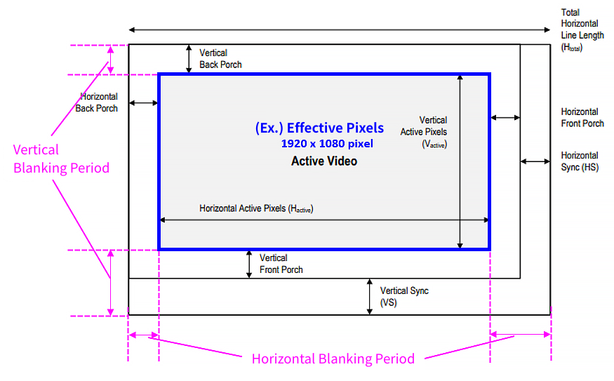
General video signals include horizontal and vertical blanking periods in addition to effective pixels. Although the blanking periods do not contain valid display image information, they are transmitted as data and must therefore be included in bandwidth calculations. The total data, including blanking periods, is generally about 1.2 times the effective pixel data.
Calculate PCLK (pixel clock) using the following formula.

PCLK = 1920 × 1080 × 1.2 × 60 = 149.3MHz
The bandwidth of the video to be transmitted is calculated with the following formula.
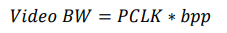
Video Bandwidth = 149.3MHz × 8bit = 1.19Gbps
Since 1.19 Gbps is less than 6 Gbps, transmission via GMSL2 is possible. However, actual GMSL2 communication involves transmitting various types of data alongside video data. Consequently, the bandwidth available specifically for video data is less than the full 6Gbps. Please check the user guide for details.
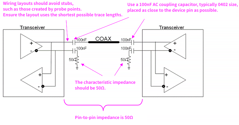
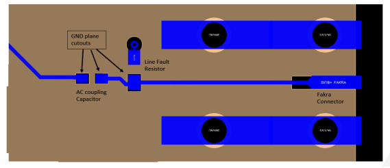
(b) GMSL Transmission Line Design Precautions
Designing the GMSL transmission line requires caution because it operates at high speeds up to 6Gbps.
The following design precautions apply when using COAX cable:
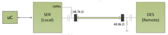
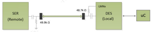
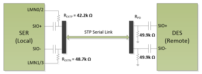
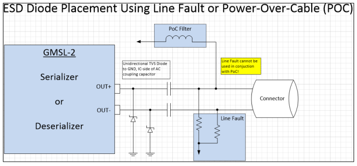
(c) Line Fault
Line Fault is a function to detect abnormalities in the GMSL transmission line. Note that the Line Fault function cannot be used simultaneously with Power Over Coax (POC), which is discussed later. By connecting voltage-dividing resistors between the GMSL line and the LMNx terminal and GND, the following abnormal states are detected.
- Short to battery
- Short to GND
- Open line
- Line-to-line short
(d) POC (Power Over Coax)
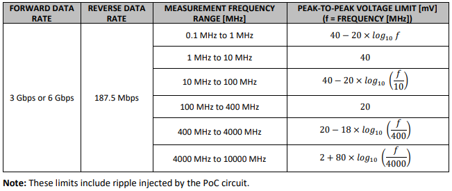
Power over Coax (POC) is a technology that allows power to be superimposed onto the COAX cable along with the data signal. For example, in applications like small camera modules where size constraints make it difficult to include a dedicated power IC, power can be supplied from the deserializer side over the COAX cable and received by the serializer side within the camera module. Although high-speed communication and power share the same COAX cable, they do not interfere with each other because a POC filter is used to separate their respective frequency bands.
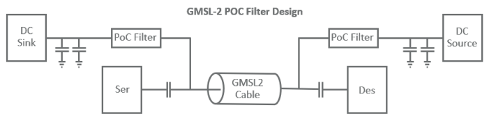
The POC filter uses inductors and resistors. The filter component values are chosen to effectively separate the low-frequency band used for power transmission from the high-frequency band used for the forward and reverse communication channels. The image is as shown below.


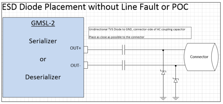
(e) ESD Protection Element
The GMSL line has an ESD protection device built into the IC. If this internal protection is insufficient for the application's requirements, an external TVS diode should be added. The characteristics required for an external TVS diode are shown below
- Capacitance of < 0.5pF or less to, prevent degradation of high-speed GMSL2 signal
- Small package footprint lo minimize capacitance
- Low breakdown voltage and low clamping voltage
- Unidirectional, reverse-biased onto, the link
- Two-port component to minimize lane-lane crosstalk
4. About Channel Specifications
The GMSL communication line operates at extremely high speeds. Failure to consider its characteristics can lead to signal attenuation and reflection, hindering proper signal reception at the receiver. Fundamentally, the GMSL transmission line is considered compliant with specifications if it meets the following channel requirements (a) through (c). Therefore, even when incorporating the previously described Line Fault, POC, or ESD protection elements, the design must still adhere to these channel specifications. Please consult the documentation for detailed information.
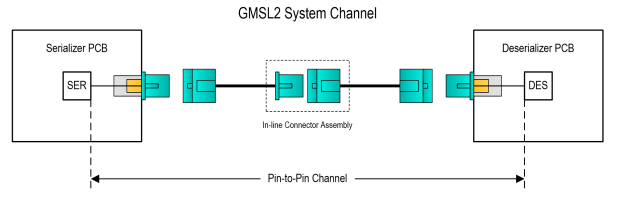
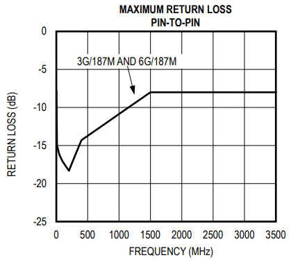
(a) Satisfy insertion loss and return loss channel specifications for the pin-to-pin configuration.
The pin-to-pin path extends from the Serializer's GMSL output pin, through the PCB wiring, connectors, and cable, arriving at the deserializer's GMSL input pin.
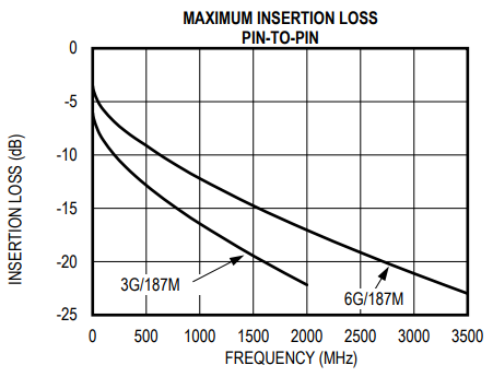
Specifically, the insertion loss must remain within negative 19.5 dB at 1.5 GHz for 3 Gbps operation, and within negative 21 dB at 3 GHz for 6Gbps operation. These specifications should ultimately be confirmed through testing on the actual device.
| GMSL2 MAXIMUM CHANNEL INSERTION LOSS PIN-TO-PIN | ||
|---|---|---|
| GMSL2 MAXIMUM CHANNEL INSERTION LOSS PIN-TO-PIN | 6 Gbps Forward ⁄ 187 Mbps Reverse | |
| APPLIED BAND | 2 MHzto 2GHz | 2 MHz to 3.5 GHz |
| INSERTION LOSS | -19.5 dB at 1.5 GHz | -21 dB at 3 GHz |
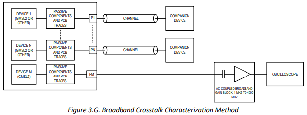
(b) Satisfy crosstalk specifications (if another high-speed transmission line is nearby).
Broadband crosstalk specifications are below: Satisfy 4 mV (p-p) from 1 to 4 GHz.
| FORWARD DATA RATE [GB ⁄ S] | REVERSE DATA RATE [MB ⁄ S] | MEASUREMENT FREQUENCY RANGE [MHz] | MAXIMUM CROSSTALK | CONDITIONS |
| 3 Gbps or 6 Gbps | 187.5 Mbps | 1 MHz to 4000 MHz | <4 mV(pp) | Interferers are any combination of high-speed links |
Narrowband crosstalk specifications are below:


(c) Satisfy link margin specifications
Gradually decrease the transmission amplitude from the initial value and check the amplitude margin until reception errors occur. An amplitude margin greater than the minimum required value in the table below is required (link margin = initial amplitude - amplitude just before a reception error occurs).
Tools are available for this verification, so please contact us for more information.
| CABLE | DATA RATE (FORWARD ⁄ REVERSE) | MINIMUM REQUIRED FORWARD CHANNEL LINK MARGIN [mV] | MINIMUM REQUIRED REVERSE LINK MARGIN [mV] |
| COAX ⁄ STP | 6 Gbps / 187 Mbps | 150mV | 90mV |
| COAX ⁄ STP | 3 Gbps / 187 Mbps | 150mV | 90mV |
Note: A link margin tool is available through the Analog Devices GMSL GUI. Alternatively, software support is available for customers to develop their own implementation of these tools in their software.
MAX96717 Product Information and Various Documents
- MAX96717 CSI-2 to GMSL2 Serializer Datasheet (PDF)
- GMSL2 Hardware Design Guide(PDF)
- GMSL2 Channel Specification User Guide(PDF)
- GMSL2 General User Guide(PDF)
- MAX96717 ⁄ F ⁄ R User Guide(PDF)
- MAX96717 CSI-2 to GMSL2 Serializer Datasheet (PDF)
- GMSL2 Hardware Design Guide(PDF)
- GMSL2 Channel Specification User Guide(PDF)
- GMSL2 General User Guide(PDF)
- MAX96717 ⁄ F ⁄ R User Guide(PDF)
Inquiry
Related Product Information
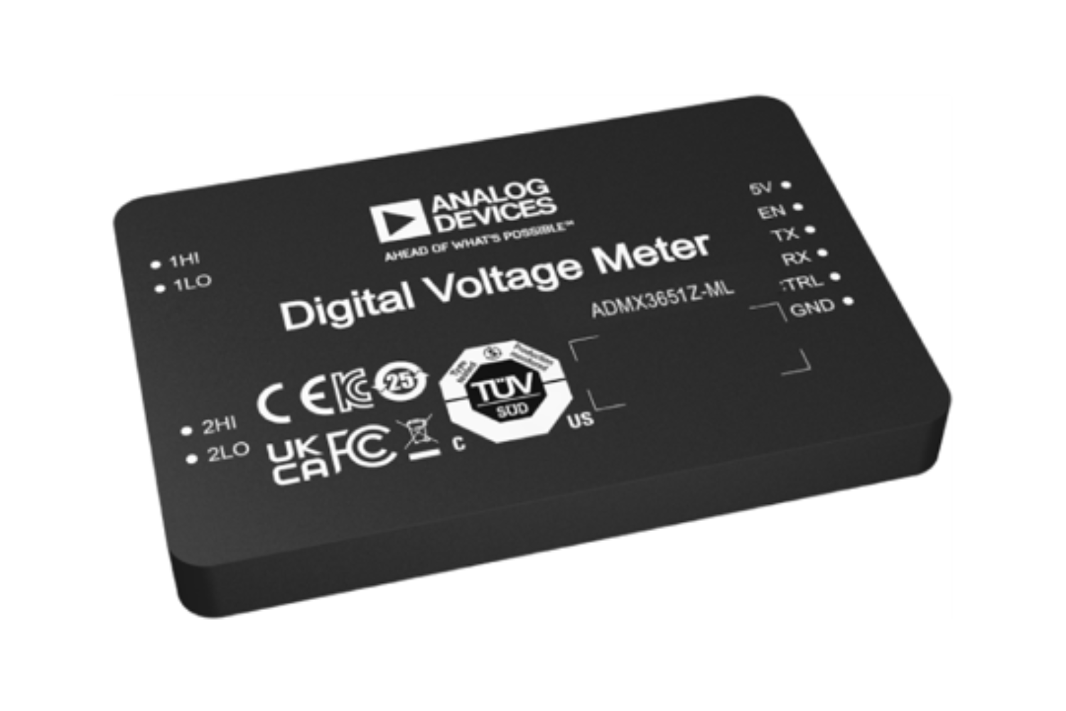
ADMX3651: 6.5-digit, ±10V digital voltmeter
The ADMX3651 is a 6½-digit digital voltmeter that combines high throughput and high-precision measurement, making it suitable for industrial automated testing and high-precision voltage measurement.
- Analog Devices, Inc.
- ICT and Industrial
LT7176: 24A/4V, single-phase or dual-phase silent switcher step-down regulator with digital power system management capabilities.
The LT7176 is a step-down regulator with a Silent Switcher that supports up to 24A output, and also features PMBus control, telemetry, and PolyPhase operation.
- Analog Devices, Inc.
- ICT and Industrial
MAX77726/MAX77727: 22V, 3A synchronous step-down converter (with ultrasonic mode)
The MAX77726/MAX77727 are high-efficiency step-down converters for ultra-low power devices. They support ultrasonic mode and I2C control.
- Analog Devices, Inc.
- ICT and Industrial
TMC2241: 65V 2-arm smart built-in stepper motor driver (with S/D and SPI)
The TMC2241 is a high-performance ROTATIONAL STEPPING MOTORS driver IC compatible with 65V. It features quiet operation and current sensing capabilities.
- Analog Devices, Inc.
- ICT and Industrial
AD5710R: 8 channels, 16-bit, configurable IDAC/VDAC with built-in reference. AD5711R: 8 channels, 12-bit, configurable IDAC/VDAC with built-in reference.
The AD5710R/AD5711R are 8-channel 12/16-bit D/A converters. They support both IDAC and VDAC, have a built-in internal reference voltage, and evaluation boards are available.
- Analog Devices, Inc.
- ICT and Industrial
- Smart Factories and Robotics
LT80602/3: 3V to 65V, 2.5A/3.5A/ SWITCHES synchronous rectification step-down Silent Switcher with 8μA quiescent current.
The LT80602/3 is a synchronous buck regulator with a quiescent current of 8μA. It offers low EMI, high-efficiency operation, and supports a wide input voltage range. An evaluation board is also available.
- Analog Devices, Inc.
- NEXT Mobility
- ICT and Industrial
- Smart Factories and Robotics
Link to Related Technical Columns

Overview of in-vehicle 48V systems and introduction of ADI SOCKETS
This session will explain the advantages and design key points of automotive 48V POWER SUPPLIES, and introduce ADI's 48V compatible POWER SUPPLIES ICs, bidirectional converters, GATE DRIVER, current detection amplifiers, and more.
Ideal for replacing PHOTOCOUPLERS! Features of digital isolators
The Coupler is a magnetically coupled digital isolator that replaces PHOTOCOUPLERS, achieving low power consumption, high-speed transmission, high CMTI, and high reliability.
Challenges and Solutions for High-Current DC-DC Converters
This is a technical explanation of how multiphase, SWITCHES, and SWITCHES capacitor technologies can be used to solve the issues of large current DC/DC converters.
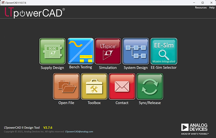
Start your smart POWER SUPPLIES design with LTpowerCAD
LTpowerCAD is a tool that supports everything from POWER SUPPLIES IC selection to circuit design, performance evaluation, and simulation collaboration, significantly improving design efficiency.

Tips for designing a stable POWER SUPPLIES: Phase margin
This section compares phase margin to delays in online games and explains control and delay countermeasures in the stable design of the LT8624S POWER SUPPLIES IC.