

- Analog Devices, Inc.
- NEXT Mobility
- ICT and Industrial
Addressing the Issue of Increased Loss in Reverse Polarity Protection Diodes
Units such as ECUs operate using power supplied by a battery, but there is a risk of accidentally connecting the battery with reversed polarity.
If the battery is connected in reverse, current flows in the opposite direction, which can damage the unit. To prevent this, protective measures are put in place.
Because diodes only allow current to flow in one direction, a typical solution is to connect a diode in series between the battery and the unit for reverse polarity protection.
However, during normal operation, current constantly flows through this diode, which leads to continuous power loss calculated as the diode's forward voltage (Vf) multiplied by the current (Iin). Figure 1
In recent years, current consumption in units like ECUs has been increasing. As a result, diode losses have also grown, leading to problems such as diode heating and reduced overall system efficiency.
Solving the Problem with Ideal Diode Controllers MAX16171 / MAX16141
To address this issue, we introduce the ideal diode controllers MAX16171 and MAX16141, developed by the former Maxim.
These controllers replace the traditional reverse polarity protection diode by controlling the ON/OFF state of a MOSFET, preventing reverse current flow and resolving the associated issues.
While the MOSFET also conducts current during normal operation and incurs some loss, this loss—calculated as Rdson multiplied by the current (Iin)—is significantly lower than that of a diode, leading to reduced heat generation and improved system efficiency. Figure 1
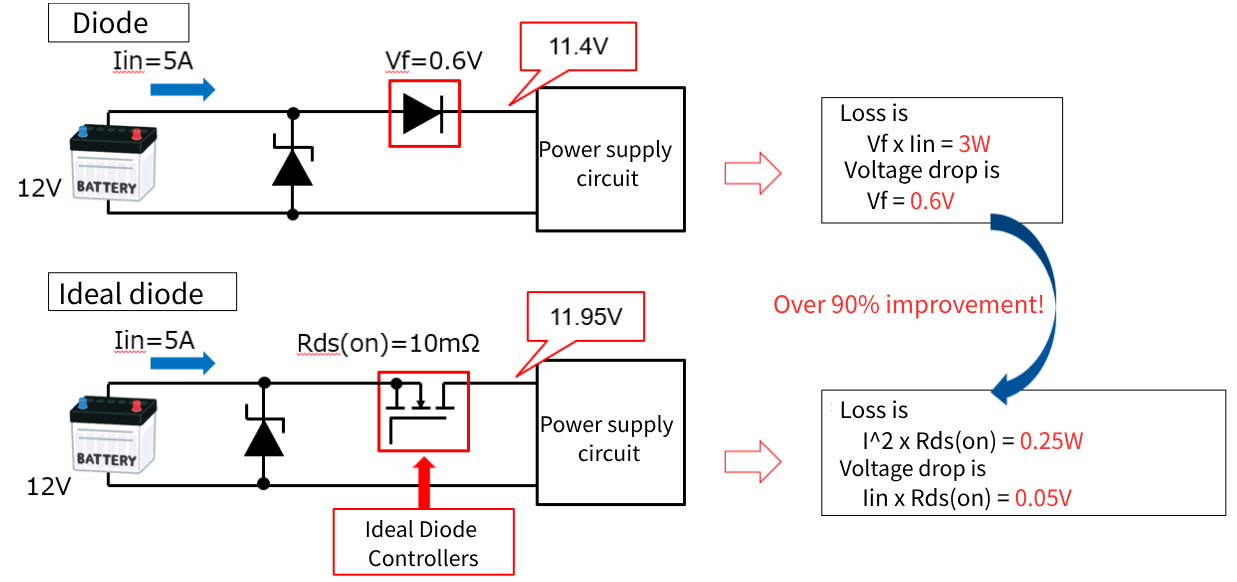
Figure 1. Comparing Reverse Polarity Protection Diodes and Ideal Diodes
The MAX16171 provides an inexpensive replacement for reverse polarity diodes using a single FET. In contrast, the MAX16141 utilizes two FETs in a back-to-back configuration. This configuration offers a more robust replacement, providing protection against forward overcurrent and overvoltage in addition to reverse polarity protection.
Table 1. Comparison Table by Solution
To address this issue, we introduce the ideal diode controllers MAX16171 and MAX16141, developed by the former Maxim.
These controllers replace the traditional reverse polarity protection diode by controlling the ON/OFF state of a MOSFET, preventing reverse current flow and resolving the associated issues.
While the MOSFET also conducts current during normal operation and incurs some loss, this loss—calculated as Rdson multiplied by the current (Iin)—is significantly lower than that of a diode, leading to reduced heat generation and improved system efficiency. Figure 1
| Reverse Polarity Protection Diode | MAX16171 | MAX16141 | |
|---|---|---|---|
| Power consumption | × | ◎ | ◎ |
| System Cost | ◎ | ◯ | △ |
| Overcurrent/Overvoltage Protection | × | × | ◯ |
Both the MAX16141 and MAX16171 feature very fast response times, quickly blocking reverse current upon detection to safely protect the system.
The MAX16141 also includes a unique feature called Sleep Mode. (Figure 2)
During sleep mode, the back-to-back MOSFETs are turned off. This allows the MAX16141, while consuming only 10 uA itself, to supply up to 400 uA of current from the battery to the downstream circuit.
-

Figure 2. MAX16141 Sleep mode
-
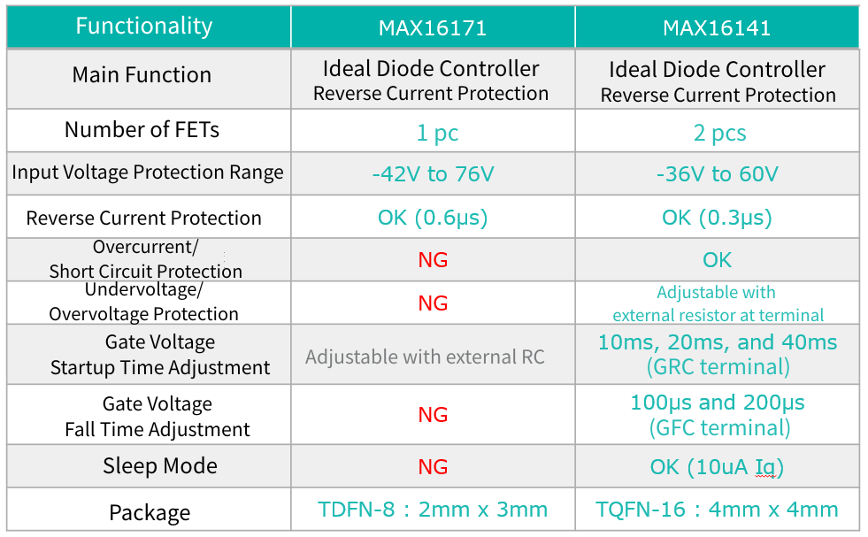
Table 2. Function Comparison Table
Inquiry
Related Product Information
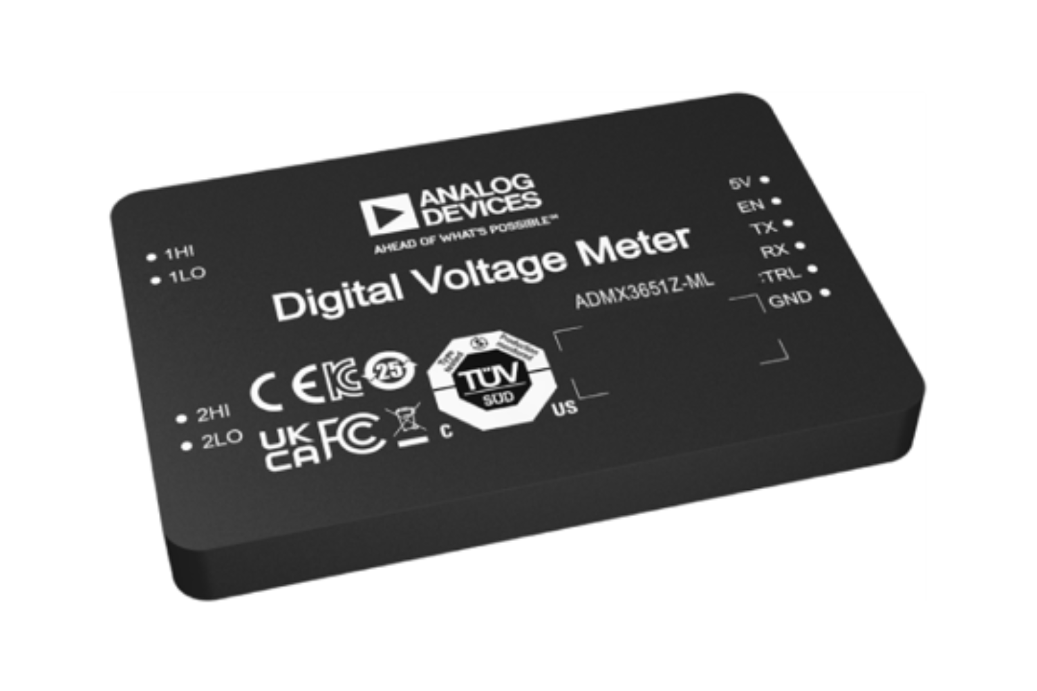
ADMX3651: 6.5-digit, ±10V digital voltmeter
The ADMX3651 is a 6½-digit digital voltmeter that combines high throughput and high-precision measurement, making it suitable for industrial automated testing and high-precision voltage measurement.
- Analog Devices, Inc.
- ICT and Industrial
LT7176: 24A/4V, single-phase or dual-phase silent switcher step-down regulator with digital power system management capabilities.
The LT7176 is a step-down regulator with a Silent Switcher that supports up to 24A output, and also features PMBus control, telemetry, and PolyPhase operation.
- Analog Devices, Inc.
- ICT and Industrial
MAX77726/MAX77727: 22V, 3A synchronous step-down converter (with ultrasonic mode)
The MAX77726/MAX77727 are high-efficiency step-down converters for ultra-low power devices. They support ultrasonic mode and I2C control.
- Analog Devices, Inc.
- ICT and Industrial
TMC2241: 65V 2-arm smart built-in stepper motor driver (with S/D and SPI)
The TMC2241 is a high-performance ROTATIONAL STEPPING MOTORS driver IC compatible with 65V. It features quiet operation and current sensing capabilities.
- Analog Devices, Inc.
- ICT and Industrial
AD5710R: 8 channels, 16-bit, configurable IDAC/VDAC with built-in reference. AD5711R: 8 channels, 12-bit, configurable IDAC/VDAC with built-in reference.
The AD5710R/AD5711R are 8-channel 12/16-bit D/A converters. They support both IDAC and VDAC, have a built-in internal reference voltage, and evaluation boards are available.
- Analog Devices, Inc.
- ICT and Industrial
- Smart Factories and Robotics
LT80602/3: 3V to 65V, 2.5A/3.5A/ SWITCHES synchronous rectification step-down Silent Switcher with 8μA quiescent current.
The LT80602/3 is a synchronous buck regulator with a quiescent current of 8μA. It offers low EMI, high-efficiency operation, and supports a wide input voltage range. An evaluation board is also available.
- Analog Devices, Inc.
- NEXT Mobility
- ICT and Industrial
- Smart Factories and Robotics
Link to Related Technical Columns

Overview of in-vehicle 48V systems and introduction of ADI SOCKETS
This session will explain the advantages and design key points of automotive 48V POWER SUPPLIES, and introduce ADI's 48V compatible POWER SUPPLIES ICs, bidirectional converters, GATE DRIVER, current detection amplifiers, and more.
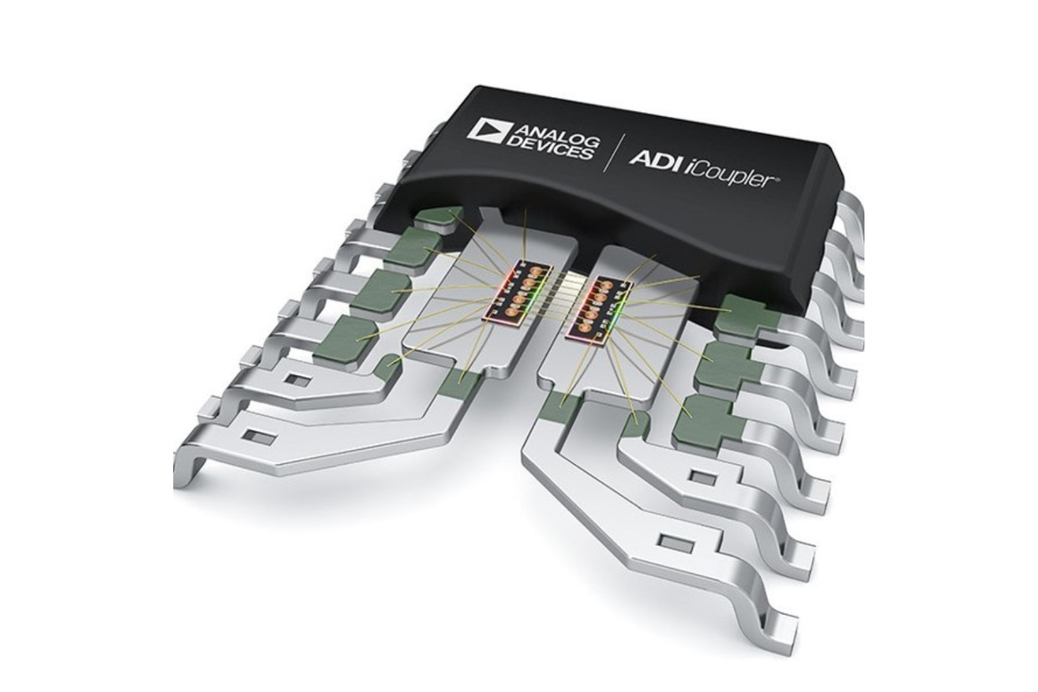
Ideal for replacing PHOTOCOUPLERS! Features of digital isolators
The Coupler is a magnetically coupled digital isolator that replaces PHOTOCOUPLERS, achieving low power consumption, high-speed transmission, high CMTI, and high reliability.
Challenges and Solutions for High-Current DC-DC Converters
This is a technical explanation of how multiphase, SWITCHES, and SWITCHES capacitor technologies can be used to solve the issues of large current DC/DC converters.
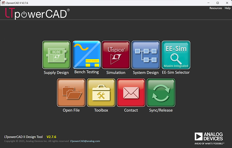
Start your smart POWER SUPPLIES design with LTpowerCAD
LTpowerCAD is a tool that supports everything from POWER SUPPLIES IC selection to circuit design, performance evaluation, and simulation collaboration, significantly improving design efficiency.

Tips for designing a stable POWER SUPPLIES: Phase margin
This section compares phase margin to delays in online games and explains control and delay countermeasures in the stable design of the LT8624S POWER SUPPLIES IC.