

- Analog Devices, Inc.
- NEXT Mobility
Managing Power Stability: Addressing Battery Voltage Fluctuations in Automotive Applications
In automotive applications, battery voltage is often stepped down from 12V for use during normal operation, but several conditions cause the battery voltage to fluctuate.
Example: During cranking, when the starter motor draws power from the battery to start the engine, a phenomenon occurs where the battery voltage temporarily drops significantly.
For this reason, a buck-boost DC/DC converter is typically used as the first power stage after the battery.
However, a known challenge with H-bridge buck-boost converters is their poor responsiveness and the resulting output voltage instability during the transition between step-down and step-up modes.
MAX20039/MAX20040 Solves the Issue
As a solution to this challenge, we introduce the MAX20039/MAX20040 from the former Maxim company.
The MAX20039/MAX20040 are H-bridge buck-boost converters that can perform seamless switching between boost and buck operation modes. They limit the voltage drop during these mode transitions to within ±3%.
Additionally, the four FETs that form the buck-boost converter are integrated into the IC, which enables a reduction in PCB size.
-
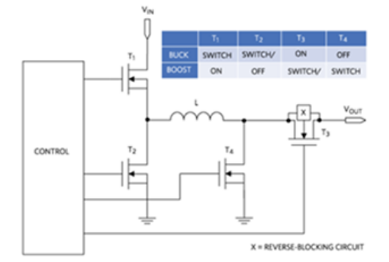
Buck-boost power train architecture and operation table
-
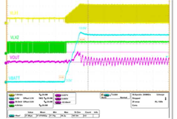
Positive line-transienr response
-
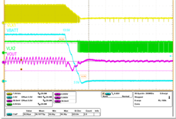
Negative line-transienr response
* Waveform diagrams and other figures are excerpted from the source below.
MAX20039 / MAX20040 Features
| / | MAX20039 | MAX20040 |
|---|---|---|
| VIN (V) (min) | 2 | |
| VIN (V) (max) | 40 | |
| VOUT1 (V) (max) | 12 | |
| IOUT1 (A) (max) | 0.6 | 1.2 |
| Switch Type | Internal | |
| Preset VOUT (V) | 5 | |
| Output Adjustment Method | Preset, Resistor | |
| Synchronous Switching? | Yes | |
| Power Good Signal | Yes | |
| # DC-DC Outputs | 1 | |
| Alternate Topology | Step-Down, Step-Up, Step-Up/Down | |
| Switching Frequency (kHz) | 200, 300, 400, 500, 1000, 2200 | |
| Design Tools | EE-Sim | |
| Package/Pins | TQFN-CU/20 | |
| Oper. Temp. (°C) | -40 to +85 -40 to +125 | |
| Budgetary Price (See Notes) | 1.95 | 2.2 |
Small Solution
600mA/1.2A output current
(1A capability @ 105°C ambient)
4.5V to 36V supply voltage (40V tolerant)
Cold crank support down to 2V input
Fixed output 3.3V/5V and 1% ref on FB pin
Adjustable FSW 220kHz to 2.2MHz
Seamless transition from buck to boost mode
PGOOD output (96% ± 2%)
SYNC input
Small 16-SW TQFN-EP 4mm x 4mm package
Efficient
Low Iq of 36μA @ VOUT 3.3V no load (EN 'hi')
Low Iq of 52μA @ VOUT 5V no load (EN 'hi')
< 10μA shutdown current (EN 'lo')
AEC-Q100, temp range: -40°C to +125°C
Availability
Stock
EvKit
MAX20040EVKIT#
Detail Link
Inquiry
Related Product Information
MAX77726/MAX77727: 22V, 3A synchronous step-down converter (with ultrasonic mode)
The MAX77726/MAX77727 are high-efficiency step-down converters for ultra-low power devices. They support ultrasonic mode and I2C control.
- Analog Devices, Inc.
- ICT and Industrial
TMC2241: 65V 2-arm smart built-in stepper motor driver (with S/D and SPI)
The TMC2241 is a high-performance ROTATIONAL STEPPING MOTORS driver IC compatible with 65V. It features quiet operation and current sensing capabilities.
- Analog Devices, Inc.
- ICT and Industrial
AD5710R: 8 channels, 16-bit, configurable IDAC/VDAC with built-in reference. AD5711R: 8 channels, 12-bit, configurable IDAC/VDAC with built-in reference.
The AD5710R/AD5711R are 8-channel 12/16-bit D/A converters. They support both IDAC and VDAC, have a built-in internal reference voltage, and evaluation boards are available.
- Analog Devices, Inc.
- ICT and Industrial
- Smart Factories and Robotics
LT80602/3: 3V to 65V, 2.5A/3.5A/ SWITCHES synchronous rectification step-down Silent Switcher with 8μA quiescent current.
The LT80602/3 is a synchronous buck regulator with a quiescent current of 8μA. It offers low EMI, high-efficiency operation, and supports a wide input voltage range. An evaluation board is also available.
- Analog Devices, Inc.
- NEXT Mobility
- ICT and Industrial
- Smart Factories and Robotics
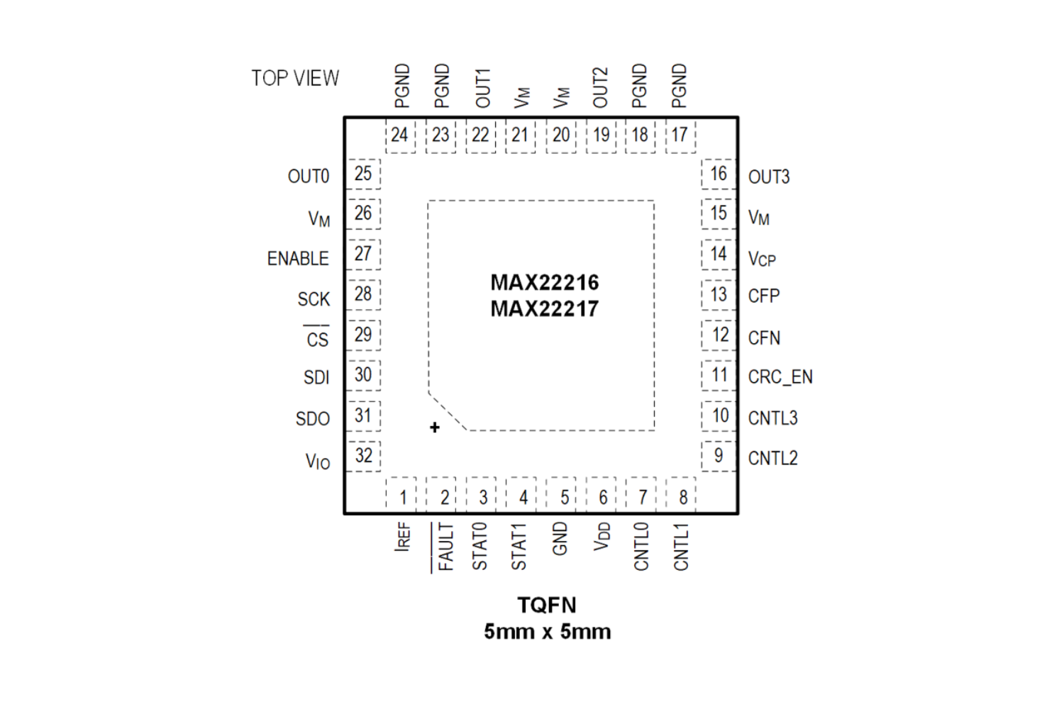
MAX22216: Quad Smart Serial Control Solenoid and Motor Driver with Advanced Diagnostic Capabilities
This is a smart driver for solenoids/DC motors with a built-in 36V quad half-bridge. It supports SPI/OTP and includes diagnostic and protection functions.
- Analog Devices, Inc.
- ICT and Industrial
- Smart Factories and Robotics
ADA4356: Configurable TRANSFORMERS impedance, current/bit receiver µModule
This is a current-input μModule with configurable TIA and LPF, and a built-in 14-bit 125MSPS ADC. It supports LVDS output, making it suitable for ToF applications, and an evaluation board is also available.
- Analog Devices, Inc.
- ICT and Industrial
Link to Related Technical Columns

Overview of in-vehicle 48V systems and introduction of ADI SOCKETS
This session will explain the advantages and design key points of automotive 48V POWER SUPPLIES, and introduce ADI's 48V compatible POWER SUPPLIES ICs, bidirectional converters, GATE DRIVER, current detection amplifiers, and more.
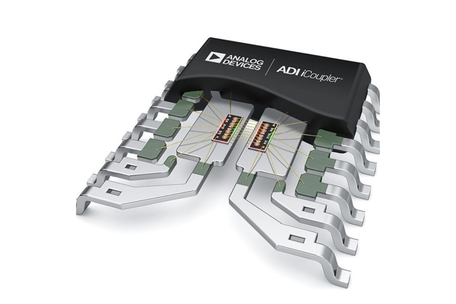
Ideal for replacing PHOTOCOUPLERS! Features of digital isolators
The Coupler is a magnetically coupled digital isolator that replaces PHOTOCOUPLERS, achieving low power consumption, high-speed transmission, high CMTI, and high reliability.
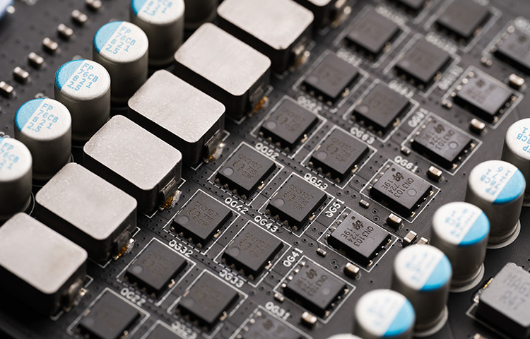
Challenges and Solutions for High-Current DC-DC Converters
This is a technical explanation of how multiphase, SWITCHES, and SWITCHES capacitor technologies can be used to solve the issues of large current DC/DC converters.
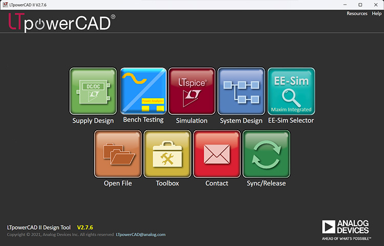
Start your smart POWER SUPPLIES design with LTpowerCAD
LTpowerCAD is a tool that supports everything from POWER SUPPLIES IC selection to circuit design, performance evaluation, and simulation collaboration, significantly improving design efficiency.

Tips for designing a stable POWER SUPPLIES: Phase margin
This section compares phase margin to delays in online games and explains control and delay countermeasures in the stable design of the LT8624S POWER SUPPLIES IC.