
Introduction
GMSL (Gigabit Multimedia Serial Link) is a high-speed, highly reliable serial communications technology developed by Analog Devices (ADI) that is primarily suitable for automotive applications, and is available as a lineup of GMSL serializer and deserializer (Ser/Des) IC products. In recent years, the resolution of in-vehicle cameras and displayed images has continued to increase, creating a demand for technology that can stably transmit higher-resolution video signals.
To meet these needs, next-generation GMSL devices are being released that can support faster data transmission speeds.
The first generation "GMSL1" has a maximum speed of 3Gbps,
The second generation "GMSL2" has a maximum speed of 6Gbps,
The third generation "GMSL3" has improved performance with a maximum speed of 12Gbps.
GMSL is high performance and has many functions, making it possible to realize even complex video applications. However, the large number of register settings can be a hurdle when first introducing it.
In addition, the GMSL communication method has changed between GMSL1 and GMSL2, and the number of registers in GMSL2 has increased compared to GMSL1, which can make configuration confusing.
The automatic script generation function built into the GMSL software provided by ADI solves these problems.
This function enables automatic generation of register settings for the GMSL2 video transmission section (video section only).
This article explains how to use the tool, aiming to reduce design time and promote understanding of how to set GMSL2 registers.
*The script auto-generation function introduced here supports Ser/Des of the CSI-2 interface.
Get GMSL SerDes Public GUI Software
First, install the "GMSL SerDes Public GUI Software" software used with the GMSL2 evaluation board. You can download the software from the following URL.
Alternatively, you can Access the download link from the "Tools and Simulation" section of the GMSL2 product page.
From the software download page, click "GMSL_SerDes_Public_GUI_V0_1_6_2_Install.zip" to obtain it.
You will need a my Analog account to download the software, so please prepare in advance and follow the instructions to create an account.
*At the time of writing, the latest version of the software is 1.6.2.

Figure 1. Software links on the MAX96716A product page

Figure 2: GMSL2 software download page
Once the download is complete, launch "GMSL_SerDes_Public_GUI_V0_1_6_2_Install.exe" in the folder to begin the installation.
Now you're ready to go.
This configuration
Using the functions of the "GMSL SerDes Public GUI Software," we will automatically generate a script with the following simple configuration.
<Specifications>
Serializer: MAX96717
Deserializer: MAX96714
Video signal: MIPI CSI-2, YUV422 8bit, VC0

Figure 3: Configuration diagram
How to use the CSI Configuration Tool
<Step 1>
Launch the installed "GMSL_SerDes_Public_GUI".
Click "CSI Configuration Tool" under "Tools" tab > "Video Config".
*If you use the CSI Configuration Tool, no hardware is required.
It can only be used with the software.

Figure 4. Starting the Configuration Tool
<Step 2> Select the deserializer to use.
Select the “MAX96714” to be used this time as the “Deserializer” in the “CSI Configuration Tool”.
If you select MAX96714, you will be able to select "Mode" and "I2C Device Address".
"Mode" selects the MIPI CSI-2 output configuration of the MAX96714.
Since the MAX96714's MIPI CSI-2 output only supports 1 Port x 4 lanes, "1x4" is automatically selected.
Some deserializers are available in multiple configurations, in which case you can select the configuration you want to use.
The initial value of "I2C Device Address" changes depending on the processing of the CFG0 TERMINALS of the MAX96714.
This time, when starting up the MAX96714, select "0x50" as the I2C Device Address.

Figure 5 Deserializer basic settings Input
<Step 3> Select the serializer to use.
If you select MAX96714 as the deserializer, you will be able to enter the serializer part number.
Since the MAX96714 has only one GMSL input, only the GMSL-A Serializer column is displayed.
If you select a deserializer with multiple GMSL inputs, the corresponding number of GMSL-A/B/C/D serializers and input fields will be displayed.
Check the checkbox to connect to the GMSL-A Serializer.
Select "MAX96717" for Serializer.
Since the MAX96717's "Mode" only supports "1x4", "1x4" will be entered automatically.
The power-up address is determined by the CFG0 TERMINALS, and in this example we select "0x80".
If you want to change the Device Address of the MAX96717 after startup, select the desired address from "Final Address".
Since we will not be changing it this time, select the same "0x80".
Finally, select the communication method.
GMSL2 has two modes: Pixel mode and Tunneling mode, and you must choose which one to use.
[Pixel mode]
This is the conventional GMSL2 communication method.
The CSI-2 CRC provided by the sensor is used for error checking in the serializer and then removed.
The serializer then replaces the data with GMSL data, adds a GMSL CRC, and sends it to the deserializer, which then performs a GMSL CRC check and converts it back to CSI-2.
The deserializer adds a new CSI-2 CRC to the converted CSI-2 signal and sends it to the downstream SoC.
This method is mainly used in general image processing.

Figure 6 GMSL2 Pixel mode
[Tunneling mode]
This is a newly added GMSL2 communication method.
The CSI-2 CRC added by the sensor is not removed, but is retained and sent to the downstream SoC via GMSL communication.
It provides comprehensive monitoring of the GMSL system, ensuring that the sensor signals are perfectly aligned with the signals reaching the SoC.
It is especially used in safety-critical applications such as ADAS.

Figure 7 GMSL2 Tunneling mode
This time we will select Pixel mode, so leave the Tunneling checkbox blank.
Now you can choose between a Serializer and a Deserializer.
Click Configure to configure the data path details.

Figure 8 Serializer basic settings Input
<Step 4> MAX96717 (Serializer) video settings
Clicking “Configure” will display a block diagram of this Serializer/Deserializer combination.

Figure 9 Serializer + Deserializer configuration diagram
From here, we will set up the video input of the MAX96717.
First, click on "CSI" to define the CSI input that will be fed into the MAX96717.
The MAX96717 only has Port-B as its MIPI CSI-2 input, so this time we will use the example of when "VC (Virtual channel) 0" data type (DT) "YUV422 8bit" is input to "Port-B".
In this example, select "0" for "Add input VC", "YUV422_8bit" for "and DT", and "B" for "on Port".
You can also change the VC within the Serializer, so if you want to change the VC, select the desired VC in "Remap VC".
This time, we will not change the VC from the CSI-2 input of VC0, so we will simply select "0" for Remap VC.
Select all items and click "Add to Port" to add a video input to the Serializer Input.
Once you have finished setting up, click the x in the upper right corner to close the CSI Input List Creation window.

Figure 10 Serializer CSI, Input list creation completed
MIPI CSI-2 can handle multiple video signals (video streams) with a single interface.
This time we are using one video input as an example, but by defining the video input in the same way, you can also create scripts for multiple inputs.

Figure 11 Example of Serializer Input when VC0 to VC3 are multiplexed
<Step 5> MIPI PHY settings for MAX96717 (Serializer)
From here, we will configure the MIPI PHY of the MAX96717.
There are two types of MIPI PHY: C-PHY and D-PHY. The MAX96714 only supports D-PHY, so select "D-PHY" in the selection box at the top left.
Next, specify the number of lanes for the MIPI CSI-2 input in Lane Cout.
Since we are assuming a 1x4 lane, select "4" for Lane Cout.
The serializer supports lane swapping and data polarity inversion.
To swap lanes, change the numbers in the Lane Map block for each Data Lane.
Data lane assignments are color-coded, so you can see at a glance how the lanes have been swapped.
If you want to invert the polarity due to the sensor or SoC, check the "Polarity Inversuion" box for the Data Lane you want to invert.
Finally, if you need a Data Lane deskew, check "Enable" for Deskew.
If it's higher than 1.5Gbps/Lane, you need Deskew, if it's below 1.5Gbps/Lane, check as needed.
In this example, we will proceed with the default settings without performing Lane Swap, Polarity Inversion, or Deskew.
When you have finished configuring, click the x in the upper right corner to close the MIPI D-PHY Rx Configuration window.

Figure 12 Serializer DPHY settings (default)

Figure 13 Polarity reversal, example of swapping Lane 3 and Lane 1
<Step 6> MAX96714 (Deserializer) video settings
From here, we will configure the video signal that the MAX96714 will receive.
Click "CSI" to select which MIPI port of the MAX96714 the MAX96714 will receive and output the video data sent from the MAX96717.
If you click the dropdown for "Route Input DT", the Serializer Input item defined in <Step 3> will appear.
In this case, there is only one video data, so select “GMSL-A PortB VC0 YUV422_8bit” for the video “Route Input DT” for which you want to specify the route.
"To Deserializer Port" determines which port on the Deserializer this video data will be output from.
Since the MAX96714 only has Port A, select "A" for "to Deserializer Port."
The "with VC" option determines how the Deserializer handles the VC of the specified video.
In this case, we will not change the VC of the video data received on VC0, so select "0" for "with VC".
If you want to change the VC on the deserializer side, select the desired VC.
Next, determine the data type (DT) with "and DT".
Normally, you will not change the data type in the middle of the process, so select the same "YUV422_8bit".
Finally, click “Add to Port” to complete the setup, and the settings made for Deserializer Output will be displayed as a list.
Set the above settings for each Serializer Input video data defined on the Serializer side.
Once the settings for all video data are complete, the message "All input DTs in the DES pipeline are routed." will change from yellow to green and you're ready to go.
When you have finished setting up, click the x in the upper right corner to close the CSI Output on Deserializer window.

Figure 14 Deserializer CSI, Port allocation completed

Figure 15: Example of settings when receiving video data VC0~3
<Step 7> MIPI PHY settings for MAX96714 (Deserializer)
This will be the last setting.
Clicking on "DPHY" will take you to the MAX96714 MIPI PHY configuration screen.
<Step 4> Configure the MIPI PHY output of the MAX96714 in the same way as configuring the MIPI PHY of the MAX96717.
The deserializer side needs to select the MIPI CLK rate, so specify the desired CLK rate.
There are two types of deskew: initial deskew, which is performed before high-speed transmission, and periodic deskew, which is performed periodically. These are required for rates higher than 1.5Gbps/Lane.
Copy from can be used when a deserializer with multiple output MIPI ports is selected.
This function allows you to copy port data. For example, you can copy video data assigned to Port A and output it from Port B.
This time, set MIPI CLK to 1000Mbps and leave everything else at default settings.
When you have finished configuring, click the x in the upper right corner to close the MIPI D-PHY Rx Configuration window.
Now all the settings are complete.

Figure 16 Deserializer DPHY settings (MIPI CLK 1000Mbps)
<Step 8> Generate the script
Click Generate Script.

Figure 17 Configuration diagram, Generate Script
Next, click "Export Script."
Decide the save location and file name and click "Save" to save the generated script.

Figure 18 Script output
Loading scripts
If you want to actually use the script you created this time on an evaluation board, first connect the MAX96717 and MAX96714 evaluation boards and have the GUI recognize them, then load the script file you created from the File tab > Load (.cpp) File, and the setting values will be written to each device.

Figure 19 Loading the created script
Finally
This time, we explained how to automatically generate GMSL2 register settings using software.
The example in this article uses a simple Ser/Des configuration, but the same method can be used to automatically generate complex configurations such as four serializers and one quad deserializer.
Only the video transmission section can be automatically generated, so when using it in an actual application, additional settings such as FSYNC generation and GPIO will be required, but the ease of creating scripts can significantly reduce design man-hours.
The "GMSL SerDes Public GUI Software" has other useful functions, so try using it together with the "CSI Configuration Tool."
Inquiry
Related Product Information

Lantronix - System on Module with Qualcomm IoT Application Processors
Lantronix provides SoMs equipped with Qualcomm IoT processors and offers end-to-end solutions utilizing AI and 5G.
- LANTRONIX, INC.
- ICT and Industrial
- Smart Factories and Robotics

An In-Depth Look at the Advantages of NXP's Automotive Microcontroller S12 MagniV
NXP’s integrated microcontroller, S12 MagniV, helps miniaturize ECUs and shorten development time, contributing to the electrification of automotive systems. This article explains its features and benefits.
- NXP Semiconductors NV
- NEXT Mobility
- ICT and Industrial

MOTIX™ Microcontroller Smart motor control. MOTIX™ is a highly integrated microcontroller that integrates drive circuits.
MOTIX™ is a highly integrated 32-bit microcontroller specialized for motor control, achieving high reliability and control precision for automotive and industrial equipment.
- Infineon Technologies AG
- NEXT Mobility

License control via CodeMeter soft files
CmActLicense, which allows license control using software files, effectively prevents illegal copying and use without the need for hardware.
- WIBU-SYSTEMS AG
- ICT and Industrial
- Smart Factories and Robotics
- Software
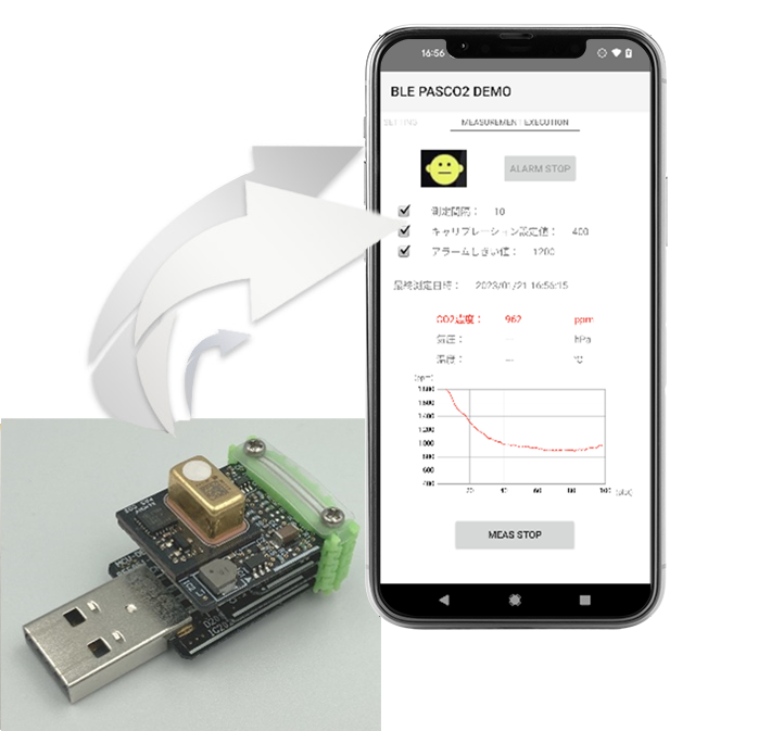
CO2 sensor demo system
Our CO2 sensor demo system transmits measured CO2 values via BLE to a dedicated Android app, and the measurement results can be displayed in graphs.
- Infineon Technologies AG
- ICT and Industrial
- Smart Factories and Robotics
Introducing CodeMeter embedded use cases: Runtime/CmEmbedded/ExProtector
CodeMeter's embedded solutions protect and license your software in a variety of environments, from PCs to RTOS-based systems.
- WIBU-SYSTEMS AG
- ICT and Industrial
- Smart Factories and Robotics
- Software