
Automotive functional safety is not simply a checklist of steps, but a series of activities that are incorporated into the design based on the assumption that failures may occur. This article is aimed at engineers involved in ECU development and explains the key points of ISO 26262, how to determine HARA and ASIL, hardware safety indicators such as SPFM, LFM, and PMHF, the IEC TR 62380 failure rate model, and even DYNAMIC RAMS memory safety mechanisms from a practical perspective that can be used to make decisions. The article is structured so that as you read, you will naturally understand why it is necessary and where it is effective.
1. Key points of ISO 26262 and its role in automotive ECUs
ISO 26262 is a functional safety standard that systematizes development processes and verification methods to suit the characteristics of the automotive industry. The scope of application was expanded from the first edition in 2011 to the second edition in 2018, making it easier to use in practice. Although it is not legally binding, it is treated as a de facto industry standard, and compliance with safety-related ECUs is generally confirmed by OEMs or third-party organizations.
In design, it is necessary to consistently establish a mechanism throughout the entire process to detect failures, determine control policies in the event of a failure, and transition to a safe state (fail-safe). The process of breaking down these requirements into specific risk levels is HARA, which will be discussed in the next chapter.

2. HARA Procedure: From S/E/C to ASIL Determination
HARA (Hazard Analysis and Risk Assessment) is a method to identify the sources of danger in a target system (item),
- Severity (S)
- Exposure frequency (Exposure: E)
- Controllability (C)
This is the process of assessing risk based on these three elements and assigning an ASIL (Automotive Safety Integrity Level: A to D).
For example, even with the same airbag function, a high ASIL is expected because incorrect deployment is likely to lead to a serious accident, while failure to deploy under certain conditions may be highly avoidable depending on the situation, resulting in a relatively low ASIL.
The safety goals derived from the evaluation are developed into a Functional Safety Concept (FSC) and reflected in the specific design of the ECU.
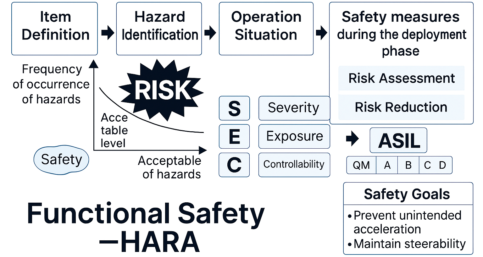
Figure 1: HARA evaluation flow and overall view of ASIL determination
3 ASIL and requirement levels
ASIL is generally determined based on OEM policies and vehicle architecture, so the required level may change even for the same function. On the other hand, if the function and usage conditions are the same, the required ASIL tends to converge to a similar level. If the functional range expands and the impact of failure becomes wider, the required ASIL may be raised. For example, when integrating a throttle into engine control, the risk of failure increases, so it may be necessary to review the ASIL.
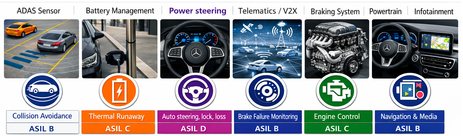
Figure 2. Example of ASIL by function (image)
4 Why failure rates are necessary: The connection between PMHF and safety design
The purpose of ISO 26262 hardware safety is to quantitatively evaluate the impact of random hardware failures on the Safety Goal and to ensure safety from the architecture stage. The three core metrics for this evaluation are SPFM, LFM, and PMHF.
-
SPFM (Single Point Fault Metric)
An index that shows how much the risk of a single point failure directly impairing the Safety Goal has been reduced. The fewer undetected single point failures there are, the higher the SPFM. -
LFM (Latent Fault Metric)
This is an evaluation index for preventing a latent failure from combining with other failures and developing into a dangerous failure mode. It is important when evaluating the reliability of a redundant configuration. -
PMHF (Probabilistic Metric for random Hardware Failures)
This is the final probability index used to evaluate whether the tolerable annual dangerous failure rate (e.g., 10⁻⁸/h or less) is met for high safety requirements such as ASIL D. It is equivalent to the final safety assessment that numerically indicates the risk of failure for the entire ECU.
ISO 26262 Hardware Safety Index and ASIL Correspondence Table
SPFM/LFM (Diagnostic Coverage Metrics)
| Metric | ASIL-A | ASIL-B | ASIL-C | ASIL-D |
|---|---|---|---|---|
| SPFM | Not relevant | >90% | >97% | >99% |
| LFM | Not relevant | >60% | >80% | >90% |
In the table above, ">XX%" means that "to meet the ASIL, a minimum coverage of this percentage or more is required."
The higher the ASIL, the stricter the requirements become.
PMHF (Permissible Failure Rate)
| ASIL | Failure Rate | FIT conversion | PMHF request |
|---|---|---|---|
| D | <10⁻⁸/h | <10 FIT | Required |
| C | <10⁻⁷/h | <100 FIT | Required |
| B | <10⁻⁷/h | <100 FIT | Advised |
| A | <10⁻⁶/h | <1000 FIT | Informative |
-
Failure Rate: (/h) is the "acceptable failure rate per hour"
-
FIT conversion: is a guideline for "number of failures per 10⁹ hours (FIT)"
-
Required: A safety requirement that is essential to achieving ASIL. Failure to achieve this will result in a violation of the Safety Goal.
-
Advised: Desirable but not required to achieve ASIL. Recommended for safety enhancement.
-
Informative: Informational, non-binding, and has no effect on requirements.
The essential reason for needing the failure rate λ
As can be seen from the above indicators, the higher the ASIL,
- Increasing demands for diagnostic coverage (SPFM/LFM)
- The acceptable range of PMHF (≒λ × undetected rate) becomes extremely small.
It has the following characteristics:
In other words, to establish PMHF, it is essential to "correctly understand the failure rate (λ) of each electronic component and quantitatively indicate the extent to which diagnosis can be performed (diagnostic coverage)."
PMHF is generally
PMHF ≒ Σ (part failure rate λ × undetected rate)
is calculated as:
Since an ECU uses many components such as ICs, passive components, and CONNECTORS, the safety of the ECU is determined by adding up the λ and diagnostic coverage of each component using FMEDA.
Why failure rate models influence safety designs
Since an accurate λ is essential for PMHF, the ISO 26262 practice asks, "Which model should be used to determine the failure rate λ?"
will always be important.
The failure rate model IEC TR 62380, based on real-world usage environments, has been used for many years in the automotive field.
- Temperature Profile
- Load conditions
- Usage time (mission profile)
It is highly regarded in practice because it can calculate a realistic λ by reflecting factors such as the above.
In the next chapter, we will explain the specific features and calculation process of IEC TR 62380.
5. Failure rate model IEC TR 62380 and calculation method
This article summarizes the key points to remember when using the IEC TR 62380 failure rate model, which has been widely referenced in FMEDA and PMHF evaluations of automotive ECUs. Additionally, we will explain the λ (failure rate) calculation process and how to reflect it in FMEDA, using the semiconductor ICs we handle as an example.
5.1 Features of IEC TR 62380
IEC TR 62380 is a technical report for predicting failure rates of electronic components, printed circuit boards (PCBs), and electronic equipment, and was developed by the International Electrotechnical Commission (IEC).
The model calculates λ based on realistic factors such as:
- Temperature profile (average temperature and fluctuation range)
- Electrical load (voltage and current stress)
- Usage patterns (on/off ratio, annual operating hours)
- Environmental fluctuations specific to in-vehicle devices (temperature cycles, vibrations, etc.)
The reason why it has long been valued in the automotive industry is that it is possible to calculate a "practical failure rate averaged over the real world" based on these influence factors.
IEC TR 62380 itself has been abolished and replaced by IEC 61709, but due to insufficient compatibility of the mission profiles, 62380 is still often referenced in the field.
5.2 Components of the failure rate λ
The failure rate λ of a semiconductor IC is mainly composed of three components:
-
Die (semiconductor body): number TRANSISTORS, process generation, junction temperature, operating life
-
Package (package structure): Heat cycle, package material, lead FRAMES, mold structure
-
EOS (Electrical Over Stress): Resistance to external stresses such as ESD and surges
These are determined by combining data provided by the IC manufacturer and the actual usage conditions (temperature, load, annual operating hours, etc.) set by the OEM or Tier 1.
5.3 Calculation method and application to FMEDA
After calculating λ according to IEC TR 62380, we proceed to the failure mode expansion in FMEDA. The calculated λ affects the following safety indicators:
-
SPFM: Evaluate whether the contribution of single point failures and residual failures has been reduced
-
LFM: Evaluating the possibility of latent failures occurring in redundant configurations
-
PMHF: Accumulate the "undetected failure rate" of all failure modes and evaluate the annual dangerous failure rate against the safety goal
As shown in Figure 3, the IEC TR 62380 model combines the contributions of the die, package, and EOS to construct λ.
This λ is the basic data for FMEDA,
"How to select a failure rate model" = "Accuracy of PMHF and validity of safety architecture"
It is so important that it is safe to say so.
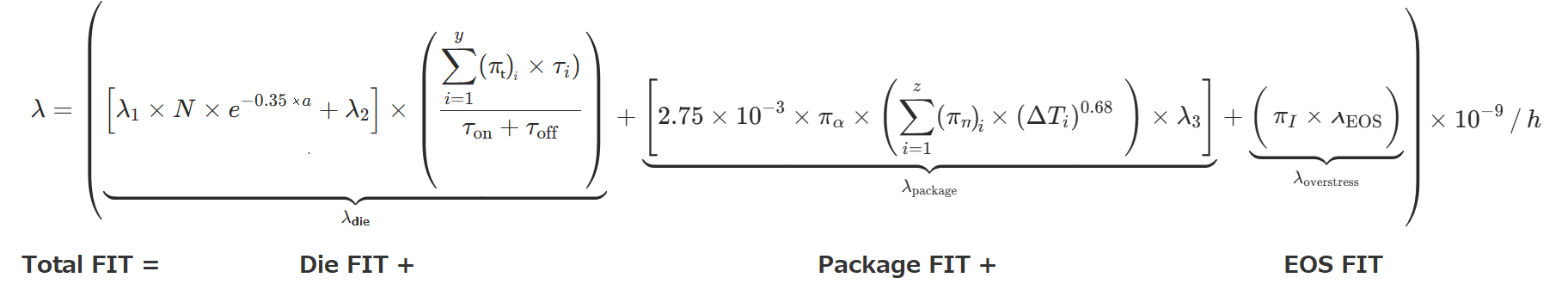
Figure 3 IEC TR 62380 failure rate model (Die/Package/EOS) Source: IEC TR 62380 standard
As described above, IEC TR 62380 is a model that has been used for many years due to its ease of use in the field, and it plays a role in supporting the foundation of FMEDA and hardware safety evaluation in ISO 26262. In the next chapter, we will delve into the safety mechanisms of DYNAMIC RAMS memory, which are particularly affected by λ.
6. Functional safety of DYNAMIC RAMS memory
In recent years, ADAS and autonomous driving ECUs have become commonplace for processing large amounts of temporary data, such as image processing, map estimation, and AI inference. As a result, memory reliability has become a factor that cannot be ignored as it affects the safety of the entire system.
In particular, there is an increasing need to treat DYNAMIC RAMS, which is the main memory, beyond its conventional position as simply a large-capacity memory, as a "critical safety component" in which errors can directly lead to incorrect judgments of sensor information and recognition results.
6.1 DYNAMIC RAMS Failure Characteristics and Safety Risks
Due to its structure, DYNAMIC RAMS has a variety of failure modes, including:
- Single-bit soft error (temporary bit flip caused by alpha rays or cosmic rays)
- Address/command line malfunction
- Data retention failure due to refresh abnormality
- Increased leakage due to cell fatigue and miniaturization
In ADAS and autonomous driving processing, huge amounts of data are continually updated on FRAMES basis, so even a momentary bit error can directly affect recognition and control decisions.
Therefore, when using DYNAMIC RAMS in an ASIL C/D system, it must be designed with the assumption that it is not a component that can be placed outside the safety mechanism.
6.2 DYNAMIC RAMS Safety Mechanisms Compliant with ISO 26262
The following safety mechanisms are becoming common in DYNAMIC RAMS products that comply with ISO 26262. These not only improve the reliability of DYNAMIC RAMS itself, but also contribute to improving diagnostic coverage in FMEDA.
-
ECC (Error Correction Code)
One-bit correction and two-bit detection corrects errors during readout in real time, making it the most effective soft error countermeasure. -
Refresh Monitoring
Detects cell data loss due to refresh abnormalities, reducing the risk of data retention failure. -
BIST (Built-in Self-Test)
This is a mechanism to detect latent faults inside memory at startup and periodically. Early screening of latent faults contributes to improving LFM (Latent Failure Mechanism). -
Address/Command Protection
Prevents incorrect Access caused by faulty wiring or control LOGIC failure. Complements safety architecture when combined with SoC. -
Safety Manual
Provides expected diagnostic coverage (DC), usage prerequisites (POWER SUPPLIES quality, temperature range, etc.), and how to account for them in FMEDA.
These safety mechanisms enable DYNAMIC RAMS to significantly reduce PMHF and improve diagnostic ease for the entire ECU system.
6.3 Precautions when applying the system
Since DYNAMIC RAMS operates as an external component in cooperation with the SoC/MCU, the system must meet the following prerequisites:
-
ECC specification conformance check
When ECC is processed on the SoC side, it is necessary to ensure consistency between the SoC's ECC function and DYNAMIC RAMS 's bit width and data structure. -
Memory controller diagnostics are now included in FMEDA
PMHF evaluates not only DYNAMIC RAMS itself, but also "controller-side diagnostics" such as address line testing, command line monitoring, and refresh monitoring. -
Design that does not violate the prerequisites of DYNAMIC RAMS safety functions
Diagnostic coverage cannot be guaranteed unless the assumptions in the Safety Manual, such as POWER SUPPLIES quality, refresh cycle, and temperature conditions, are met. -
DC (detection coverage) is now included in PMHF calculations
By reflecting the DC of the safety function in FMEDA, the PMHF of the entire ECU can be correctly evaluated.
In modern ADAS/autonomous driving ECUs that handle large-volume data processing, DYNAMIC RAMS is becoming a component that makes a significant contribution to all PMHF, SPFM, and LFM.
By selecting DYNAMIC RAMS with appropriate safety features and designing the SoC/ECU to meet the prerequisites, it is possible to operate ASIL D-class systems in accordance with safety requirements.
Summary
ISO 26262 is a common language that enables the safety of automotive ECUs to be explained across processes from the perspective of "why that safety mechanism is necessary."
HARA systematically identifies risks and clarifies the required level using ASIL. Furthermore, a system is in place to quantitatively evaluate the validity of the architecture using hardware safety indicators such as SPFM, LFM, and PMHF.
In hardware safety, random component failures cannot be ignored, and calculating λ (failure rate) using a correct failure rate model is a prerequisite for establishing a safety architecture. IEC TR 62380 has a long history of practical use as a model for determining failure rates that reflect actual usage conditions, and is a highly reliable approach for providing basic data for FMEDA and PMHF.
Furthermore, in recent ECUs for ADAS and autonomous driving, the safety of DYNAMIC RAMS memory is directly linked to the safety of the entire system.
By appropriately selecting DYNAMIC RAMS equipped with safety mechanisms such as ECC, refresh monitoring, and BIST, and incorporating these mechanisms into FMEDA in combination with the SoC's diagnostic functions, high reliability can be ensured even in ASIL C/D class system designs.
lastly
In this article, we have organized the basics of ISO 26262, as well as DYNAMIC RAMS safety mechanisms, in a way that can be used for practical decision-making.
Compliance with safety standards is not simply a matter of checking items, but an activity that ensures consistency and transparency in design decisions.
Our knowledge can also be useful for more specific application methods such as component selection, safety mechanism considerations, and FMEDA construction.
Please feel free to contact us for assistance with product specifications and evaluation materials.
Inquiry
Related Product Information

Software Protection and Licensing with CodeMeter
Wibu-Systems' AxProtector provides strong encryption of the entire software, supporting a wide range of code, including Python and Nvidia Jetson.
- WIBU-SYSTEMS AG
- ICT and Industrial
- Smart Factories and Robotics
- Software
eMMC
Micron's eMMC offers high-speed data processing and a power-saving design, making it an ideal storage solution for use in industrial equipment and robotics.
- Micron Technology, Inc.
- NEXT Mobility
- ICT and Industrial
- Smart Factories and Robotics
License control via CodeMeter soft files
CmActLicense, which allows license control using software files, effectively prevents illegal copying and use without the need for hardware.
- WIBU-SYSTEMS AG
- ICT and Industrial
- Smart Factories and Robotics
- Software

Qualcomm IoT Application Processors for the Connected Intelligent Edge
Qualcomm's IoT Application Processors leverage AI and 5G to deliver a variety of IoT solutions, including robotics and smart cameras.
- Qualcomm Technologies, Inc.
- NEXT Mobility
- ICT and Industrial
- Smart Factories and Robotics

NOR FLASH MEMORIES Infineon SEMPER™ NOR Flash boasts the highest level of safety and reliability, from automotive to industrial
SEMPER™ NOR Flash is a highly durable and reliable automotive and industrial memory with ASIL-B compliance and a long-term supply guarantee.
- Infineon Technologies AG
- NEXT Mobility
- ICT and Industrial
- Smart Factories and Robotics

An In-Depth Look at the Advantages of NXP's Automotive Microcontroller S12 MagniV
NXP’s integrated microcontroller, S12 MagniV, helps miniaturize ECUs and shorten development time, contributing to the electrification of automotive systems. This article explains its features and benefits.
- NXP Semiconductors NV
- NEXT Mobility
- ICT and Industrial