This is a technical blog by the development team at Nexty Electronics. We will be sharing information about software development using reference boards that utilize the products we handle.
This time, as a continuation of the previous blog post, we will create software for inter-task communication using a reference board equipped with an STMicroelectronics MCU (hereinafter referred to as the STM version reference board) developed by our company and FreeRTOS.
1. What we will create (goal) in this article
FreeRTOS is run on the STM version reference board, and inter-task communication is performed as follows:
- Passing "data" via a queue
- A semaphore (Binary Semaphore) is used to convey a "signal (timing)".
We will create a sample that allows you to visually confirm this using only the blinking of four LEDs.
This article will be completed without any interruptions or coordination (task-to-task communication only).
2. Expected Audience and Assumptions
- It can be built and programmed with IAR EW.
- This gives you a feel for FreeRTOS's "Tasks," "Delays," and "Priorities."
- The LED is Active Low (it lights up when GPIO=0).
3. Usage environment
| Name | Purpose | Remarks | |
|---|---|---|---|
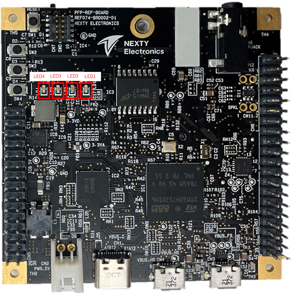
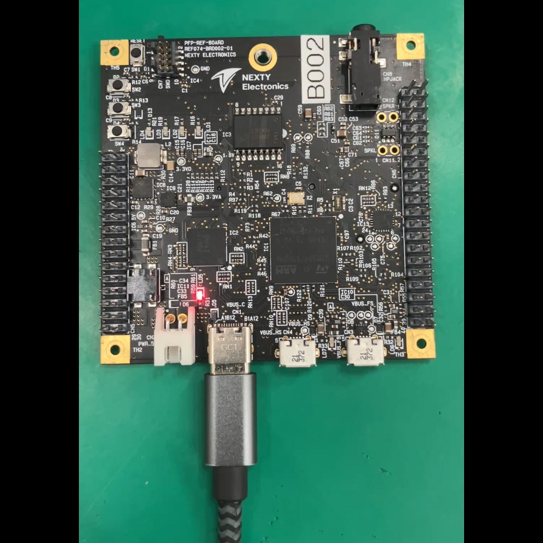
| ST version reference board | Board used | Built-in MCU: STM32H753XIH6 | 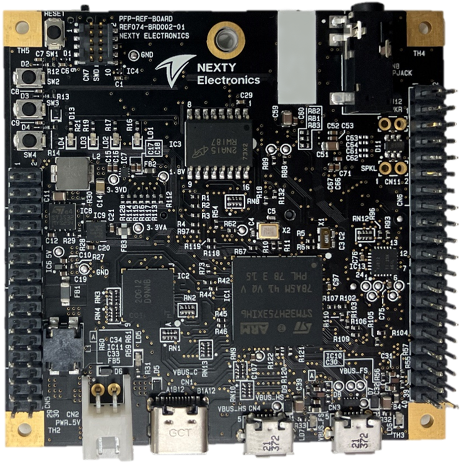
|
| I-jet | Firmware Writing Debugger | Ver: B | 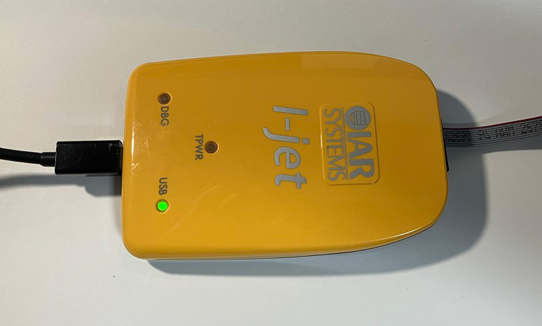 Official website |
| STM32CubeMX | Initialization Code Generation Tool | Ver: 6.12.1 | Official website |
| IAR Embedded Workbench for Arm | IDE | Ver: 9.30.1 | Official website |
4. Specifications for the entire sample (decide the behavior first)
4.1 LED Assignment (What to use the four LEDs for)
- LED1: Heartbeat (System status check)
- LED2: Blinks upon receiving a queue signal (data-driven)
- LED3: Blinks when Semaphore is released (event-driven)
- LED4: Status indicator (toggles when queue transmission fails)
4.2 LED Control Guidelines (Active Low)
Because it is Active Low, the meaning of GPIO is as follows:
- Lighting: HAL_GPIO_WritePin(..., GPIO_PIN_RESET)
- Turning off the light: HAL_GPIO_WritePin(..., GPIO_PIN_SET)
This sample provides the following helpers in main.c
static void LED_On(GPIO_TypeDef *port, uint16_t pin)
{
  HAL_GPIO_WritePin(port, pin, GPIO_PIN_RESET);
}

static void LED_Off(GPIO_TypeDef *port, uint16_t pin)
{
  HAL_GPIO_WritePin(port, pin, GPIO_PIN_SET);
}

static void LED_Toggle(GPIO_TypeDef *port, uint16_t pin)
{
  HAL_GPIO_TogglePin(port, pin);
}
Additionally, the initial output value during GPIO initialization is set to all LEDs off (SET) to prevent the LEDs from remaining lit immediately after startup.
HAL_GPIO_WritePin(GPIOK, GPIO_PIN_5|GPIO_PIN_4|GPIO_PIN_6|GPIO_PIN_3, GPIO_PIN_SET);4.3 Task Configuration (No Interrupts)
This sample demonstrates how to handle task queues and semaphores using the CMSIS-RTOS2 API (cmsis_os.h).
- StartDefaultTask (LED1): Heartbeat
- PatternProducerTask: Create a blinking pattern for LED2 and send it to the queue.
- LedDriverTask: Receives a queue and blinks LED2.
- SyncTask: Gives a semaphore (signal) at regular intervals.
- SemBlinkTask: Takes a semaphore and blinks LED3.
4.4 Expected appearance (operational image)
- LED1: Flashes with a 500ms cycle (always moving)
- LED2: The pattern changes every second, with the number of flashes changing from 1→2→3→5…
- LED3: Blinks briefly at a 700ms cycle.
- LED4: Toggles only if queue transmission fails (normally it is not expected to change).
5. Inter-task communication in queues: design and implementation
In this context, a queue is a mechanism for passing data (messages) between tasks.
In other words,
- The sending task puts the "what needs to be done" into a message and places it in a queue.
- The receiving task retrieves the message from the queue and processes it as instructed.
This allows for a division of labor.
Even for small processes like LED control,
- LOGIC (higher level) that determines the flashing pattern
- LOGIC that actually interacts with the GPIO (lower level)
This allows for separation, improving visibility as the scale increases.
5.1 Criteria for deciding whether to use a queue (difference from a semaphore)
Queues are basically used when you want to pass the data itself.
Suitable for queues
- I want to pass parameters (numbers, structures, command IDs, etc.).
- I want the receiving end to execute the processing in a specific order (I need a sequential execution).
- I want to buffer the data (store it up and process it later).
Suitable for semaphores
- A simple signal like "Wake up and process it" is sufficient (there's little need to hand over the data).
- The purpose is synchronization or mutual exclusion.
5.2 Data Design for Queues
The blinking instructions for LED2 are expressed in the following three ways.
- blink_count: How many times does it blink?
- on_ms: lighting time
- off_ms: Lights-off time
typedef struct
{
  uint16_t blink_count;
  uint16_t on_ms;
  uint16_t off_ms;
} LedBlinkMsg_t;
The queue is created with a depth of 4.
Here, "depth 4" means that up to four unprocessed messages can be stored. Increasing the depth allows the system to "accommodate slightly faster senders," but it also increases memory consumption.
g_led2Queue = osMessageQueueNew(4, sizeof(LedBlinkMsg_t), NULL);5.2.1 Blocking Time and CPU Load
RTOS queue APIs often allow you to "wait (block) if empty" or "wait (block) if full."
In this sample,
- Receiver: Waits with osWaitForever (i.e., sleeps until an event occurs)
- Sender: Block time 0 (= Give up if full)
That is our policy.
If the receiving end can block, it won't consume CPU resources while waiting (only idle tasks will run). Conversely, polling (checking repeatedly using a while loop) tends to waste CPU time unnecessarily.
5.2.2 Strategy when the queue is full (drop/wait/overwrite)
The queue typically becomes full in the following situations:
- The sender is too fast
- The receiving end is too slow (heavy processing, low priority, etc.).
The policy when the storage is full depends on the app, but there are three common options:
- Drop (this sample): Send with a block time of 0, and discard if it fails (visualized with LED4).
- Wait: Set a block time and wait until an opening becomes available (this ensures delivery, but increases delays).
- Overwrite: If only the latest value matters, use a different mechanism (shared variable + mutual exclusion/notification, etc.).
In demonstrations like the LED flashing, "dropping it isn't fatal," so if it fails, we simply use LED4 to visualize the error.
5.3 Implementation: Sending side (PatternProducerTask)
The sender sequentially submits several flashing patterns to a queue.
- Use osMessageQueuePut()
- If transmission fails (e.g., queue full), LED4 will toggle to allow visual confirmation.
const LedBlinkMsg_t patterns[] = {
  { .blink_count = 1, .on_ms = 80,  .off_ms = 120 },
  { .blink_count = 2, .on_ms = 80,  .off_ms = 120 },
  { .blink_count = 3, .on_ms = 80,  .off_ms = 120 },
  { .blink_count = 5, .on_ms = 40,  .off_ms = 60  },
};

const osStatus_t st = osMessageQueuePut(g_led2Queue, &msg, 0U, 0U);
if (st != osOK)
{
  LED_Toggle(LED4_GPIO_Port, LED4_Pin);
}
5.4 Implementation: Receiving side (LedDriverTask)
The receiving end waits using osMessageQueueGet() and blinks LED2 according to the content of the received data.
if (osMessageQueueGet(g_led2Queue, &msg, NULL, osWaitForever) == osOK)
{
  for (uint16_t i = 0; i < msg.blink_count; i++)
  {
    LED_On(LED2_GPIO_Port, LED2_Pin);
    osDelay(msg.on_ms);
    LED_Off(LED2_GPIO_Port, LED2_Pin);
    osDelay(msg.off_ms);
  }
}
There are two key points.
- Blocking the waiting period (osWaitForever) prevents unnecessary CPU usage.
- Since it's Active Low, there's no risk of confusing ON/OFF (this is handled by a helper function).
5.4.1 Reasons for "not looking at the queue while flashing" in this sample
LedDriverTask does not retrieve new messages while blinking. This means that the longer the blinking process lasts, the slower the reception will be, and the more likely the queue is to fill up.
This design is,
- When the queue is full, you can see it on LED4 (easy to observe)
- This allows you to experience what happens when the receiving end is slow (a design trade-off).
That is the intention.
If you want to "always reflect only the latest commands" in a real application,
- The blinking process is further divided into smaller parts, and the queue is checked periodically.
- Alternatively, configure it to "retain only the latest instructions".
These are some possible improvements.
6. Inter-task synchronization using semaphores (Binary Semaphores): Design and Implementation
6.1 What we want to solve with semaphores
Semaphores are used as a signal to indicate "it's okay to act now."
What's being used here is a Binary Semaphore (state of 0/1),
- When released (given), it's like "the signal has come."
- When you acquire (take), it means "I received the signal."
This is how it will be treated.
6.1.1 Properties of Binary Semaphores (Beware of Event Backlogs)
A binary semaphore can only hold a maximum value of 1. Therefore, if Release is repeated consecutively...
- Even if you release it twice, you'll only accumulate a maximum of one release.
Therefore, it is not suitable for purposes such as "counting all events."
In this example, we simply want to blink LED3 occasionally, and there's no need for the event to be strictly unmissable, so a binary semaphore is just right.
*If you want to count events without losing the event count, Counting Semaphore or Queue (insert event ID) are good options.
In this sample, SemBlinkTask
- When nothing is happening, let them sleep (block).
- When the signal is received, LED3 will flash briefly.
This is the action we will perform.
6.2 Implementation: Give side (SyncTask)
The binary semaphore is generated as follows (initial count 0):
g_semBlink = osSemaphoreNew(1, 0, NULL);SyncTask releases periodically.
Here, we are creating a period using osDelay(700),
- If periodic accuracy is critical, use the equivalent of osDelayUntil (the osDelayUntil function in CMSIS-RTOS2).
- If you need multiple periodic events, consider using a software timer.
These are common occurrences in practical work.
(void)osSemaphoreRelease(g_semBlink);
osDelay(700);
6.3 Implementation: Take side (SemBlinkTask)
SemBlinkTask waits for osSemaphoreAcquire().
Because it's blocked by osWaitForever, it doesn't consume CPU until a signal is received. This is a very important way to create a "wait" state and is one of the advantages of using an RTOS.
if (osSemaphoreAcquire(g_semBlink, osWaitForever) == osOK)
{
  LED_On(LED3_GPIO_Port, LED3_Pin);
  osDelay(50);
  LED_Off(LED3_GPIO_Port, LED3_Pin);
}
7. Summary: When to use queues and semaphores
- Queue: Passes data (parameters such as how many times to blink, how many milliseconds, etc.)
- Semaphore: A signal (indicating the timing of when it's okay to proceed).
Even with simple I/O like LEDs,
- Instructions (data)
- Timing (signal)
Designing it in separate parts makes the task structure easier to understand.
8. Appendix
8.1 Main APIs (those used in this example)
This article's implementation uses the CMSIS-RTOS2 API.
- Task creation: osThreadNew
- Delay: osDelay
- Queues: osMessageQueueNew / osMessageQueuePut / osMessageQueueGet
- Semaphore: osSemaphoreNew / osSemaphoreRelease / osSemaphoreAcquire
*The xQueueSend and xSemaphoreTake APIs listed in the table of contents are native FreeRTOS APIs, but depending on the CubeMX configuration, they may be implemented using the CMSIS-RTOS2 wrapper API. In this case, we have standardized on CMSIS-RTOS2 to match the implementation in main.c.
8.2 Operation Verification Checklist
- The LED does not stay lit immediately after POWER SUPPLIES-on (the initial Active Low value is appropriate).
- LED1 blinks with a period of 500ms.
- The blinking frequency of LED2 changes periodically (queue operation).
- LED3 blinks briefly at a cycle of approximately 700ms (semaphore synchronization).
- If LED4 is constantly blinking, the queue transmission has failed (insufficient queue depth, slow receiver, etc.).
9. Conclusion
This time, as a continuation of the previous blog post, I explained inter-task communication using queues and semaphores in FreeRTOS.
Although it uses a minimal configuration of just four LEDs, this setup allows you to experience the fundamentals of RTOS design—such as "passing data" and "passing signals"—by relating the code to its behavior.
In actual product development, more complex elements are added, such as interrupt coordination, DMA, multiple I/O control, and combinations with communication stacks, but the underlying concepts remain the same as in this sample.
The Nexty Electronics Development Team provides product development and technical support for STMicroelectronics products, so please feel free Inquiry.