- Vishay Intertechnology, Inc.
- ICT and Industrial
- Smart Factories and Robotics
"Doesn't conduct electricity, just releases heat!" Next-generation heat dissipation path
This device explains an insulated thermal jumper. Made of aluminum nitride, it simultaneously provides high thermal conductivity, insulation, and low capacitance, ensuring that only heat is released, making it suitable for a variety of applications, from RF to POWER SUPPLIES. This page explains the features, use cases, lineup, and selection methods (thermal conductivity/case size/connection pattern) with examples.
ThermaWick® features: insulation, high thermal conductivity, and low capacitance
ThermaWick® is a thermal jumper made of aluminum nitride (AlN) with a thermal conductivity of 170 W/mK, providing powerful heat dissipation. Simply adding one of these will lower the heat source temperature and extend its lifespan. It has the following four features:
- It has high electrical insulation properties so it does not interfere with signal or POWER SUPPLIES lines.
- Because of its low parasitic capacitance (0.07 to 0.26 pF), it can also be used for RF and high-speed SWITCHES applications.
- It has passed reliability tests equivalent to AEC-Q200 and is compatible with automotive and industrial equipment.
- The sizes range from 0603 to 2512, making it easy to add to existing layouts.
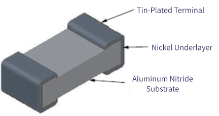
Figure 1. Structural diagram
Use Cases - Why ThermaWick® for This Application
ThermaWick® is ideal for applications that only transfer heat, not electricity. For example, it is effective for localized heat dissipation around microcontrollers and power devices, heat diffusion for LED DRIVER and FETs, and temperature stabilization for RF circuits. While conventional thermal vias have problems such as EMI noise, ThermaWick® can form an insulated heat path. Another major benefit is that it can be easily added later, reducing design change costs.
Table Comparison of heat control methods
| merit | Disadvantages | |
|---|---|---|
| Thermal vias | Easily releases heat | Potential difference, EMI risk, difficult to retrofit |
| Added copper foil | Low wiring resistance | Major layout changes required |
| Therma Wick® | Insulating, low capacity, retrofittable | Multiple units required for high power |
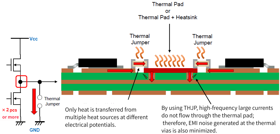
Figure 2. Thermal diffusion of ThermaWick®
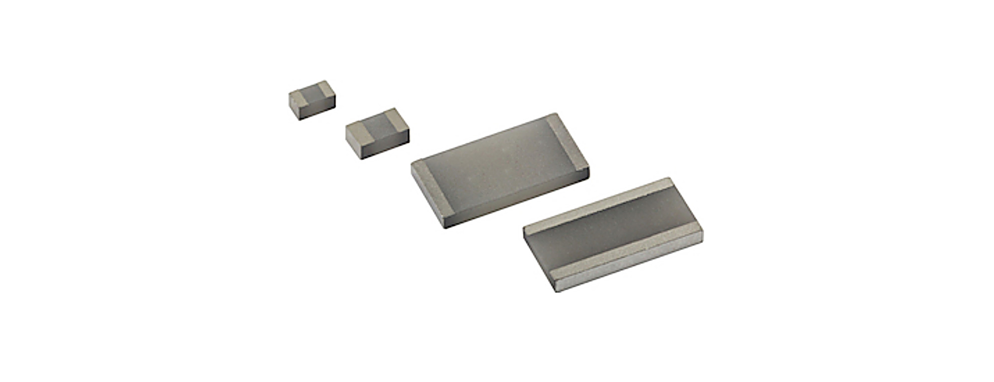
Lineup and main specifications
The lineup is as shown in the table below. These case sizes are available as standard, and thermal conductivity performance can also be selected according to size.
The operating temperature range is −65 to +150°C, and TERMINALS finishes are SnPb and Pb-free. Custom sizes and long-edge types are also available, allowing for flexible selection according to the application.
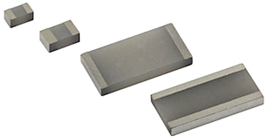
Figure 3. Appearance image
Table: Lineup comparison (Model number: THJP)
| CASE SIZE | 0603 | 0612 | 0805 | 1206 | 1225 | 2512 |
|---|---|---|---|---|---|---|
| Thermal Resistance (°C/W) | 14 | 4 | 13 | 15 | 4 | 15 |
| Thermal Conductance (mW/°C) | 70 | 259 | 77 | 65 | 259 | 65 |
| Capacitance (pF) | 0.07 | 0.26 | 0.15 | 0.07 | 0.26 | 0.07 |
| Dielectric Withstanding Voltage kV AC, RMS (60 Hz) | > 1.5 | > 1.5 | > 1.5 | > 1.5 | > 1.5 | > 1.5 |
Key points for selection and implementation: Select based on distance, area, and route
It is important to shorten the distance from the heat source to the heat dissipation destination and ensure sufficient copper area for the heat dissipation destination. If necessary, place multiple units in parallel to further increase thermal conductivity. This can be improved without adding copper foil or thermal vias, so it is also effective for modifying existing boards.
In addition, like regular chip components, it is reflow compatible, ensuring mass production.
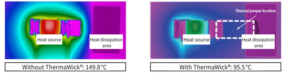
Figure 4. Comparison of thermal camera images (temperature reduction of 6W resistor by approximately 36%)
Inquiry
Related Product Information
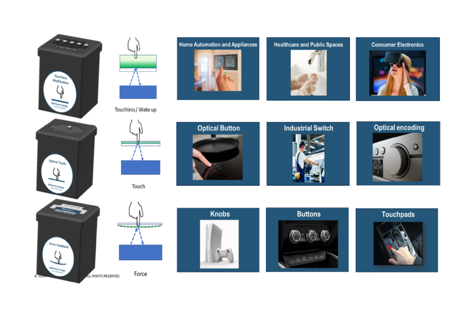
PHOTOSENSORS Reference Design: Next-Generation HMI Evolving with Optical Sensing — A Thorough Explanation of Three Methods: Touchless, Optical Touch, and Force Sensing —
This presentation introduces Vishay's Reference Design for optical sensing HMIs and explains the key design points for non-contact, optical touch, and force detection.
- Vishay Intertechnology, Inc.
- NEXT Mobility
- ICT and Industrial
- Smart Factories and Robotics
- Design, development and mass production support
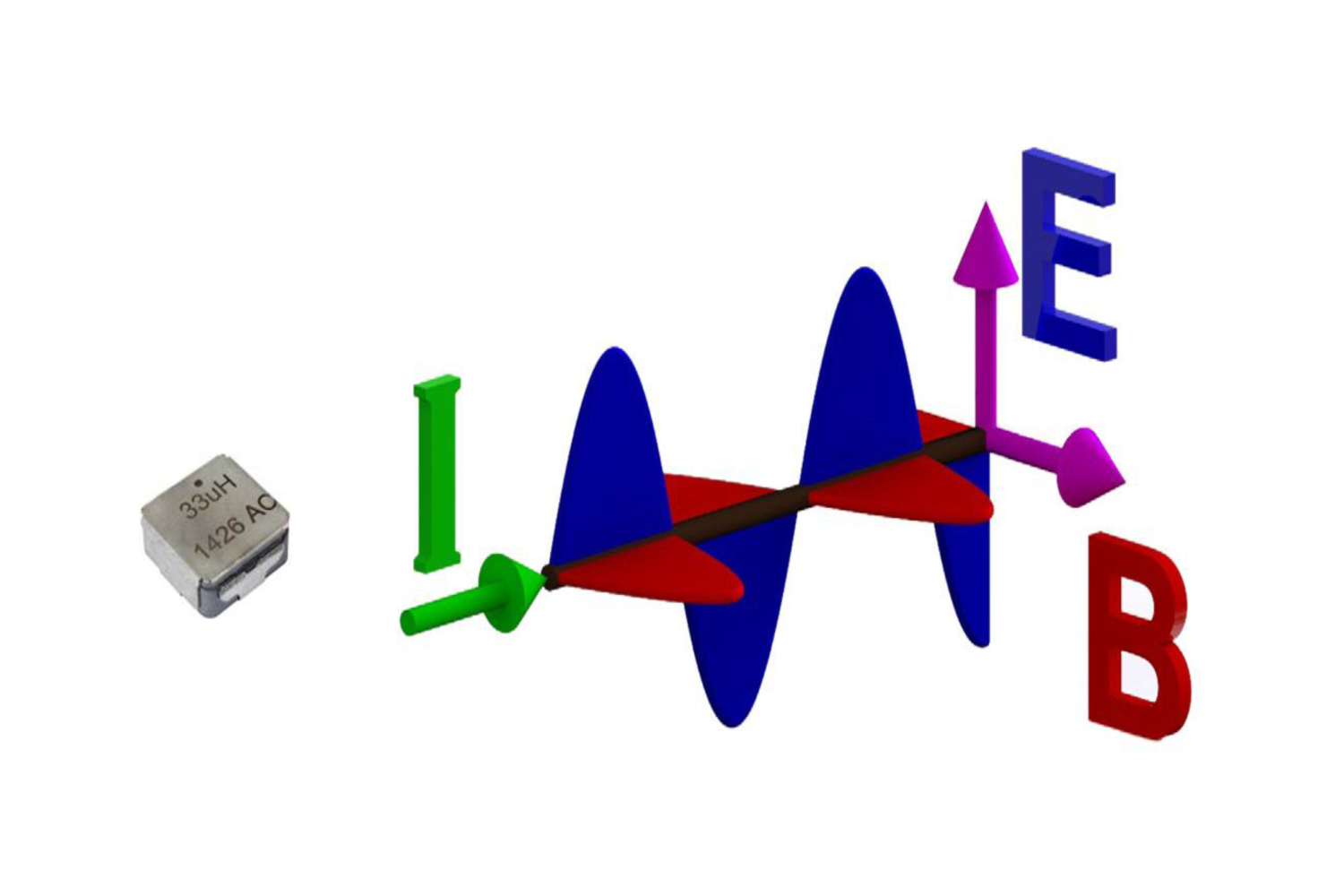
What is the power of Vishay IHLE® electric field shielded power INDUCTORS? A next-generation solution that combines EMI countermeasures with space-saving designs
IHLE is a next-generation INDUCTORS with an integrated electric field shield, a technology that significantly reduces EMI without the need for an external shield, increasing design freedom and efficiency for automotive and industrial applications.
- Vishay Intertechnology, Inc.
- NEXT Mobility
- ICT and Industrial
- Smart Factories and Robotics
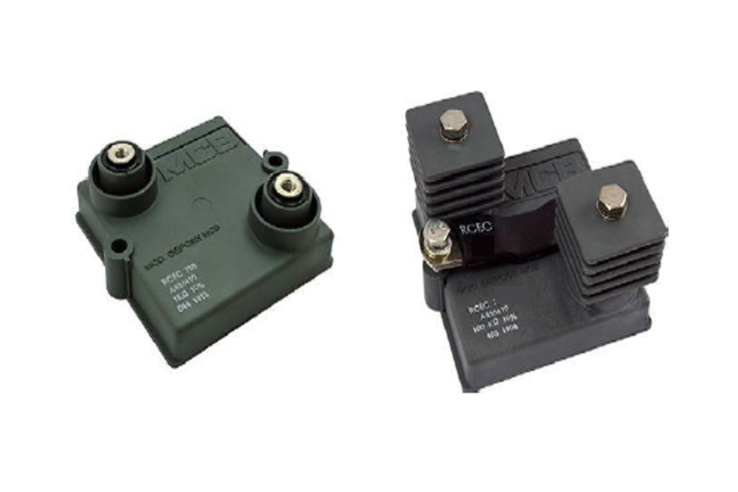
Technical Overview of the RCEC2000 Thick Film Power RESISTORS High voltage resistance, low INDUCTORS, and water-cooling compatibility for greater design flexibility (Scheduled for release after Q3 2026 - Advance information)
We will first explain the features and design advantages of the RCEC2000, which combines high voltage resistance, low INDUCTORS, and high heat dissipation.
- Vishay Intertechnology, Inc.
- NEXT Mobility
- ICT and Industrial
- Smart Factories and Robotics
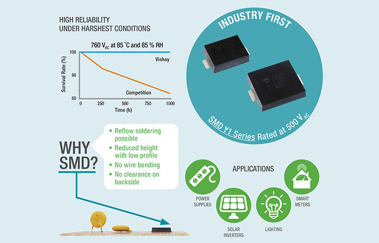
Vishay's "SMDY1 Series," the industry's first SMD Y1 CERAMICS CAPACITORS, delivers highly reliable EMI protection and insulation safety
Vishay's SMD Y1 CERAMICS safety CAPACITORS offer both EMI protection and high insulation, making them suitable for automotive and industrial applications.
- Vishay Intertechnology, Inc.
- NEXT Mobility
- ICT and Industrial
- Smart Factories and Robotics
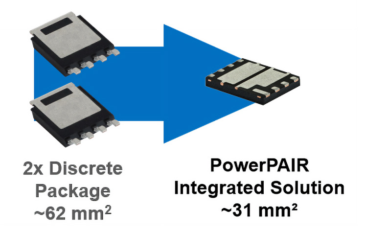
PowerPAIR® Delivers High-Efficiency, High-Power-Density MOS FETS Power Stages—An Integrated Solution Accelerating Next-Generation DC/DC Converter Design
This product is a half-bridge that integrates high-side and low-side MOS TRANSISTORS, and achieves high efficiency, high power density, and high reliability suitable for automotive applications by reducing parasitic INDUCTORS.
- Vishay Intertechnology, Inc.
- NEXT Mobility
- ICT and Industrial
- Smart Factories and Robotics
Supporting power conversion in the era of high-efficiency, high-frequency applications: Vishay FRED Pt® GEN7: A highly reliable rectifier with an ultra-fast trr of 45 ns and low Qrr
Vishay FRED Pt GEN7 is an AEC-Q101 compliant DIODES with low Qrr, low VF, and ultra-fast trr, suitable for high-frequency POWER SUPPLIES such as automotive PFC and INVERTERS.
- Vishay Intertechnology, Inc.
- NEXT Mobility
- ICT and Industrial
- Smart Factories and Robotics