
In recent years, there has been a demand for highly reliable and efficient power control in a variety of fields, including automotive systems, industrial equipment, and IoT devices. Intelligent Power Devices (IPDs) are attracting attention as a technology that can meet these needs. IPDs achieve space savings, improved design efficiency, and high safety that were not possible with conventional DISCRETE configurations. This column provides an easy-to-understand explanation of the basic structure of IPDs, their representative protection and diagnostic functions, the benefits of introducing them, and their main application areas, and explores the appeal of IPDs, which will bring new options to future power control design.
What is an IPD (Intelligent Power Device)?
An IPD is a functional SWITCHES device that integrates power SWITCHES, control circuits, and protection and diagnostic functions onto a single semiconductor chip. By integrating functions that were previously comprised of multiple DISCRETE components into a single chip, reliability, space savings, and design efficiency have been significantly improved. We will explain each of the three blocks that make up an IPD.
-
Power SWITCHES section: Controls the on/off of large currents using MOS FETS, IGBTS, etc. This enables efficient and fast power supply to the load.
-
Control circuit section: Includes GATE DRIVER and LOGIC circuits, accurately controls the operation of the power SWITCHES, and realizes SWITCHES in response to external signals.
-
Protection and diagnostic functions: Includes built-in protection circuits and self-diagnostic functions to detect abnormal conditions such as overheating, overcurrent, overvoltage, and reverse polarity, and prevent damage to devices and systems.
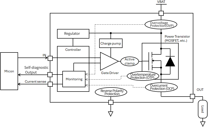
Figure: Example of an IPD's internal circuit block
Typical protection and diagnostic functions
In systems that operate in harsh environments, such as in automobiles and industrial equipment, even the slightest abnormality can lead to serious failures and safety risks.
This is where the protection and diagnostic functions built into IPDs come in. These functions instantly detect abnormalities such as overheating, overcurrent, and reverse connection, acting as a "last line of defense" to protect devices and systems.
The diagram below lists the typical protection and diagnostic functions implemented in IPDs.
Understanding why these features are needed and how they work will lead to safer and more reliable designs.
| Functionality | the purpose | Detailed explanation |
|---|---|---|
| Overheat Protection (thermal shutdown) | Shuts off output when temperature rises to prevent damage | An internal TEMPERATURE SENSORS detects abnormal temperature rise and automatically SWITCHES off to prevent damage to the device. |
| Overcurrent protection | Limits or shuts off overcurrent, includes short circuit protection | It detects momentary and sustained overcurrents to protect the circuit, and quickly shuts off the circuit in the event of a short circuit. |
| Overvoltage Protection | Protects the device from abnormally high input voltage | It detects abnormal voltage on POWER SUPPLIES line and operates to prevent damage to the device. |
| Reverse polarity protection | Protection against reversed POWER SUPPLIES polarity | This prevents reverse current from flowing due to POWER SUPPLIES supply connections, ensuring the safety of the entire circuit. |
| Active Clamp | Absorbs the back electromotive force of inductive loads to prevent damage | It absorbs the back electromotive force generated by inductive loads such as motors and relays, preventing damage to SWITCHES elements. |
| Self-diagnosis output | Notifies an external microcontroller of load abnormalities and protective actions | It monitors the internal state and outputs a signal when an abnormality is detected, contributing to improving the reliability of the entire system. |
Feature summary comparison table
IPD protection operation flow
The following protection operation flow diagram clearly shows the order in which the IPD determines the status, when it shuts down SWITCHES, and how it notifies the outside world of a self-diagnosis signal when an abnormality such as reverse connection, overvoltage, overcurrent, or overheating occurs. We will use this flow diagram to explain the IPD's protection operation flow step by step.
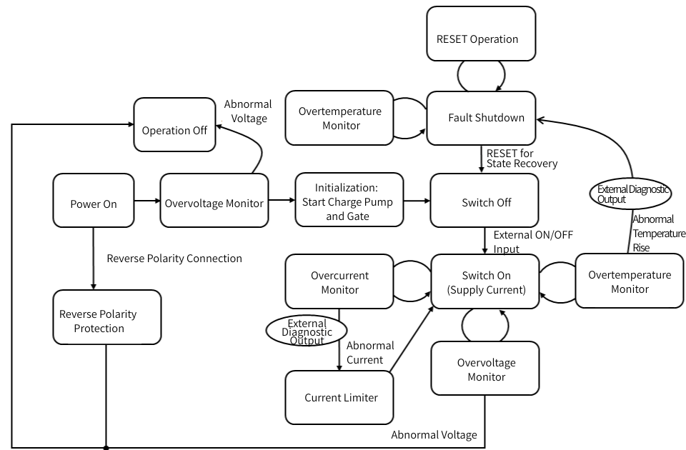
Figure: Protection function operation flow
POWER SUPPLIES-on and initial check
When POWER SUPPLIES is applied, the IPD first checks whether the + and - terminals are connected correctly through the reverse polarity protection circuit.
- In case of reverse polarity connection: The circuit is interrupted to protect the internal devices and no current will flow.
- If polarity is correct: Proceed to next step, overvoltage monitor.
An overvoltage monitor then checks whether POWER SUPPLIES voltage is within the allowable range. If the voltage is out of range (abnormal voltage), the device is turned off and no SWITCHES occurs.
Initialization and GATE DRIVER startup
If the voltage is normal, the IPD will enter internal initialization.
- GATE DRIVER startup
- Charge pump startup (boost mechanism required for high-side drive)
Once initialization is complete, the device enters a "wait" state to receive an ON/OFF signal from the external MCU.
External ON command → SWITCHES on
When an external "ON" signal is input, the IPD transitions to SWITCHES state (supplying current to the load).
At this point, the following two monitoring functions are active simultaneously:
- Overcurrent Monitor
- Overheat Monitor
If either of them detects an abnormality, the IPD immediately takes protective action.
If an abnormality occurs during monitoring
When an overcurrent is detected
If the overcurrent monitor detects an abnormal value, it will take the following action:
- The current limiter works to limit the current
- At the same time, an abnormality is notified to the external MCU via the Diag output.
When an overvoltage occurs
If the overvoltage monitor detects an abnormality again, the following action will be taken.
- All operations stopped
Abnormal temperature rise (overheating)
If the overheat monitor detects an abnormal temperature, it will take the following action:
- Instantly SWITCHES off
- The status changes to "Abnormal stop (protective action)"
- External diagnostic output
Abnormal stop → State recovery (reset)
If an abnormal shutdown occurs due to overheating or overcurrent, the IPD will stop SWITCHES for safety reasons.
To recover from this state, the following conditions must be met:
- RESET command by external MCU or POWER SUPPLIES cycle
- Check if the temperature has returned to normal
Normal operation will resume when any or all conditions (depending on the product and settings) return to normal.
Self-diagnosis signal timing chart
This timing chart shows how the IPD controls the current, temperature, and self-diagnosis signals to ensure safety when it encounters a short circuit on the load side. Looking at the sequence of events from immediately after a short circuit occurs to recovery, we can see that the IPD's internal protection circuit and diagnostic functions operate in close coordination. We will explain this in order, starting with the occurrence of an output ground fault.
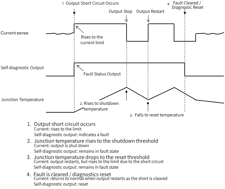
Figure: Timing chart of self-diagnosis signals
1. Output ground fault occurs
When a short circuit occurs, the output current first rises suddenly. The IPD's internal current detection circuit quickly detects this sudden change and switches to limiting the current so that it does not exceed the allowable range. On the waveform, it may appear that the current that was about to rise suddenly has "topped out," but this is an important operation to prevent damage to the element. At this point, the self-diagnosis output switches to a level that indicates an abnormal condition, and the IPD clearly notifies the external microcontroller that an "abnormality has been detected."
2. The junction temperature rises to the shutdown temperature.
Even if the current is limited, if the short circuit condition continues, the junction temperature inside the element will gradually rise. When the temperature reaches the thermal shutdown threshold, the IPD prioritizes safety and forcibly turns off the output. From this point, the current drops to zero, but the self-diagnostic output continues to indicate an abnormality. This is to reliably notify the host system that "the temperature was too high and the device stopped," and that "the cause of the abnormality may still remain."
3. The junction temperature drops to the reset temperature
When the output is turned off, the element gradually cools, and when the temperature drops below the threshold, the IPD internally returns to a state where it can operate again. At this point, depending on the product and settings, the IPD will either automatically recover, or latch off and remain in the off state until instructed to do so. This example shows the operation in the case of automatic recovery. Because the short-circuit condition has not been corrected, limited current flows immediately and the junction temperature begins to rise again. The self-diagnostic output also remains abnormal. In the case of latch-off products, the decision to recover is left to an external microcontroller, allowing the designer to create their own control LOGIC.
4. Clear abnormal status and reset diagnostic output
Resetting the diagnostic output will return the self-diagnostic output to a normal level.
Also, after the short circuit is removed, the current returns to normal when the function temperature drops below the threshold.You can see that the current sense does not remain stuck at the limit value, but instead returns to a gentle normal load current.
Benefits of IPD
By adopting IPDs, power control systems will evolve to become more high-performance and efficient. They offer many advantages not available with conventional DISCRETE configurations, such as improved reliability, space savings, and reduced design man-hours. The main benefits of IPDs are summarized below.
-
Improved reliability: Built-in protection functions prevent damage even in abnormal conditions, ensuring stable system operation.
-
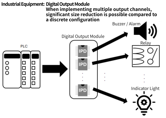
Compact size and space saving: By consolidating multiple DISCRETE components into a single chip, the mounting area on the board is significantly reduced.
-
Reduced design time: Eliminates the need to design and adjust external protection circuits, contributing to shorter development times and reduced costs.
-
Quiet and highly efficient: Because it is a semiconductor SWITCHES with no mechanical contacts, it operates quietly and enables efficient power control.
-
High-speed response: Electronic control enables high-speed SWITCHES, contributing to improved control precision.
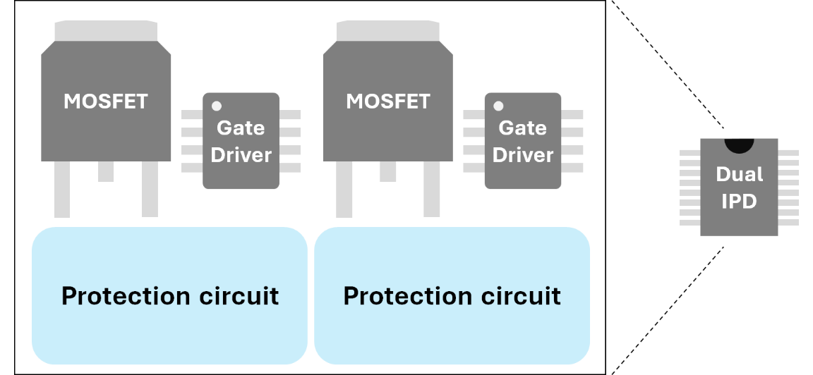
Figure: Comparison of space-saving examples
Main application areas
IPDs achieve safety, comfort, and power savings in a wide range of applications, from automotive systems to industrial equipment and even IoT devices. Below are some of the main application areas.
-
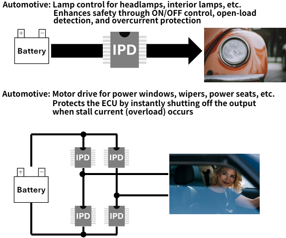
Automotive applications: Smart power distribution systems, headlights, wipers, heater controls, motor and solenoid drives, and other key components that support vehicle safety and comfort.
-
Industrial and consumer applications: Applicable to power control of a wide range of devices, including power tools, surveillance cameras, printers, and brushless DC motor drives for home appliances.
IPDs, which combine reliability with advanced protection functions, will likely become increasingly indispensable in the future for power control in automotive and industrial equipment as it becomes increasingly electrified and smarter.
Summary
IPDs (Intelligent Power Devices) are high-performance SWITCHES devices that integrate power SWITCHES, control circuits, and protection/diagnostic functions onto a single chip. Compared to conventional DISCRETE configurations, IPDs can save space, reduce design man-hours, and achieve high reliability, all at the same time, leading to their adoption in a wide range of applications, including automotive, industrial equipment, and IoT. IPDs are a new option for power control designs that require safety and efficiency. If you're interested, please Inquiry NEXTY Electronics.
Inquiry
Related Product Information
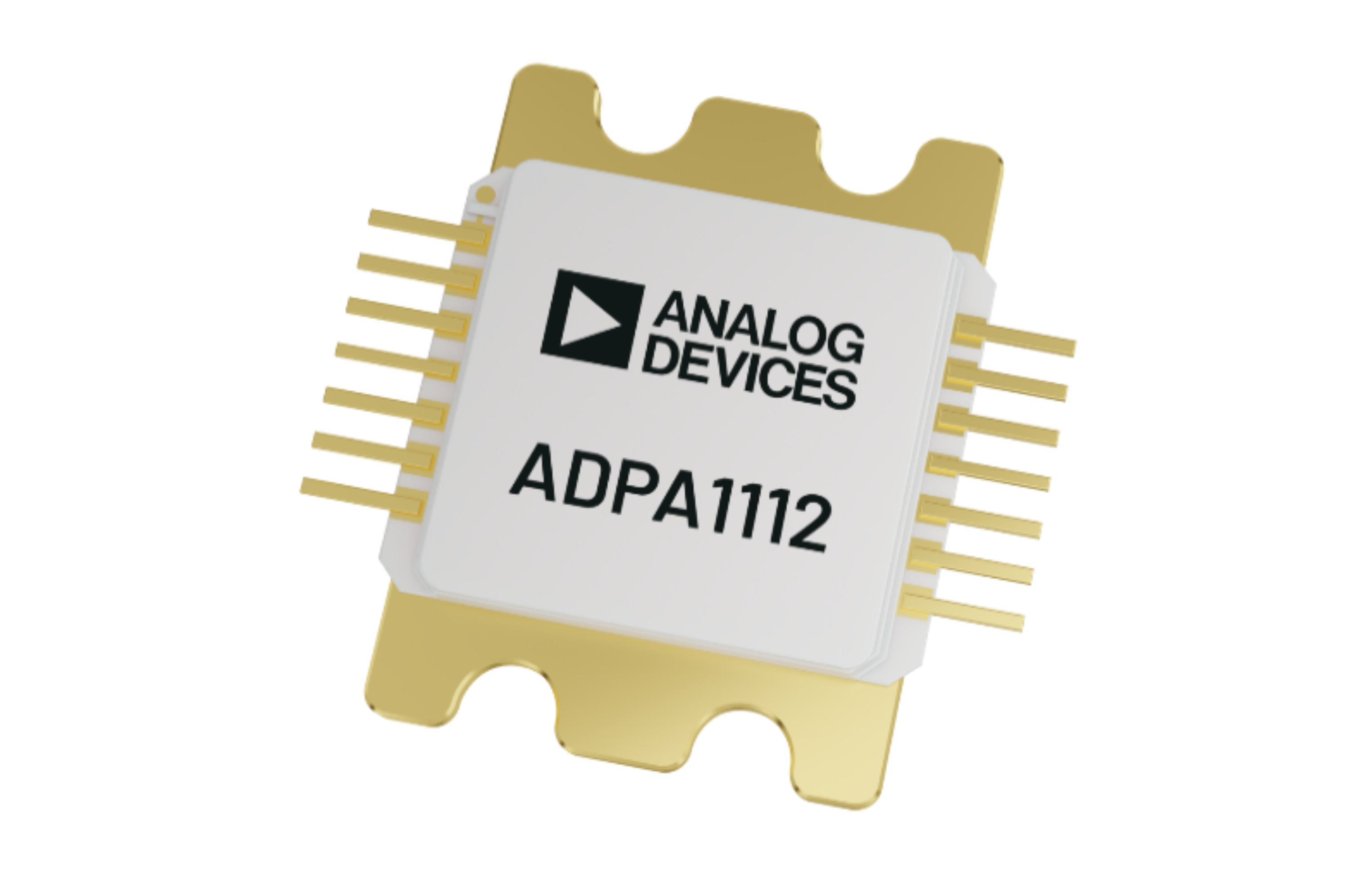
ADPA1112: 1 GHz to 22 GHz, 15 W, Gallium Nitride (GaN) Power Amplifier
The ADPA1112 is a GaN high-output RF power amplifier that operates in the 1 GHz to 22 GHz band, and offers high output and high efficiency for electronic warfare and measurement applications, as well as evaluation boards and models.
- Analog Devices, Inc.
- ICT and Industrial
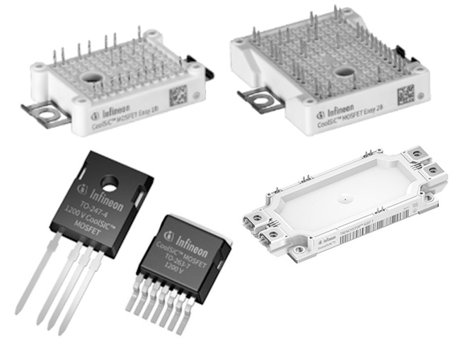
Solutions for low, medium and high power motor drives
The motor speed is controlled by varying the frequency and voltage of the motor signal, with power ranging from a few hundred watts to a megawatt.
- Infineon Technologies AG
- ICT and Industrial
- Smart Factories and Robotics

ワイヤレスジェスチャーセンサーのご紹介 (アナログ・デバイセズ製品ユースケース)
ネクスティ エレクトロニクスが開発した、ワイヤレスタイプのジェスチャーセンサーは、低コストで遠隔での家電やディスプレイ製品の制御に対応できます。
- Analog Devices, Inc.
- NEXT Mobility
- ICT and Industrial
- Smart Factories and Robotics
LT83401/2: 42V, 1A/2.5A Step-Down Silent Switcher 3 with Ultralow Noise Reference
The LT83401/2 are 42V synchronous step-down regulators with an ultralow noise internal reference. Utilizing Silent Switcher 3 technology, they deliver both high efficiency and low EMI.
- Analog Devices, Inc.
- ICT and Industrial

Key points of GMSL2 design
This article explains the features and design key points of Analog Devices' next-generation GMSL, GMSL2.
- Analog Devices, Inc.
- NEXT Mobility
Detects brightness with an in-vehicle PHOTOSENSORS VEML6031
The VEML6031 automotive PHOTOSENSORS responds accurately to the speed of sports cars and can measure a wide range of brightness, from sunlight to light passing through low-transmittance glass.
- Vishay Intertechnology, Inc.
- NEXT Mobility