
- NXP Semiconductors NV
- NEXT Mobility
NXP’s automotive PMICs (Power Management ICs) are advanced power management devices engineered specifically for automotive applications. They are the ideal solution for users seeking high efficiency, reliability, compact form factor, optimized power control, and enhanced development productivity.
In this two-part article, we will explore the necessity of PMICs in automotive ECUs, and provide a detailed overview of the features, advantages, and product portfolio of NXP’s automotive PMICs.
Page 1: Basics of PMICs and Features of NXP's Automotive PMICs.
About PMICs
What is a PMIC (Power Management IC)
With the advancement of vehicle electrification and autonomous driving technologies, automotive ECUs (Electronic Control Units) are now required to deliver high processing performance capable of handling real-time data and complex algorithms.These ECUs are equipped with high-performance processors (SoCs: System on Chips), safety microcontrollers (MCUs), and FPGAs (Field Programmable Gate Arrays).To achieve such performance, the cores—essentially the brains of these components—must operate at higher clock speeds, which in turn increases power consumption.Since battery life directly affects the driving range of electric vehicles, it is essential to not only boost processing power but also reduce power consumption.Additionally, because space inside a vehicle is limited, ECUs must also be compact in size.

Let’s take a closer look at the power requirements of automotive ECUs.
Processors include high-speed cores and memory, high-precision ADCs, and I/O and communication interfaces that require compatibility and noise resistance. They are supported by peripherals such as DDR memory and physical communication layers.To power both the processor and these components, multiple voltage rails ranging from 0.7V to 4V are needed, depending on technical standards and semiconductor process technologies.
In automotive ECUs, it is essential to monitor and manage power supplies with a high level of safety. To ensure the processor operates reliably, each power rail must stay within the voltage range required for proper functioning. Additionally, to prevent damage to the device, power must be turned on and off in a specific sequence defined by the system’s requirements. If any abnormality or fault is detected in the power supply, the system must immediately transition to a safe state to protect both the hardware and the overall vehicle operation.
A PMIC (Power Management IC) integrates these functions into a single chip.
A PMIC (Power Management IC) integrates multi-channel power, voltage monitoring, power control, and safety features into a single chip. By replacing complex power systems built with discrete ICs, PMICs help improve power efficiency, power density, and overall system optimization. With advanced integration of power rails and control functions, PMICs enhance development efficiency and enable lower power consumption and smaller ECU designs.
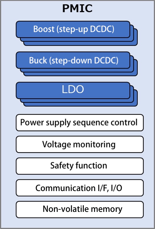
Figure 1: Automotive PMIC Designed for Functional Safety
Differences in Power Architecture Between Discrete ICs and PMICs
Differences between discrete ICs and PMICs.
It's shows examples on Figure 2 of processor power configurations using discrete ICs and PMICs.
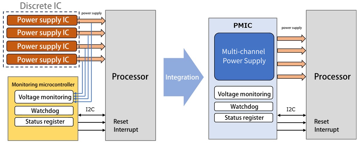
Figure 2: Simplifying the Power System with a PMIC
When processor power is built with discrete ICs (Figure 2, left), multiple power ICs and a monitoring MCU are required.
The monitoring MCU checks power voltages and sends interrupts or resets to the processor when faults are detected. The processor communicates with the MCU via I²C for watchdog control and status register monitoring.
When processor power is configured with a PMIC (Figure 2, right), multiple power ICs and the monitoring MCU can be integrated into a single chip. PMICs include multi-channel power, voltage monitoring, and watchdog functions. Using a PMIC simplifies the previously complex processor power system.
Next, we’ll explain the challenges of using discrete ICs for processor power and the advantages of using PMICs.
4 Challenges of Discrete IC-Based Power Systems
When building a processor power system with discrete ICs, the following four challenges typically arise.
- Simplifying the power system: A large number of power ICs increases circuit complexity. Managing multiple ICs with different specifications requires significant development effort.
- Adaptability to specification changes: Each spec change requires circuit updates.
- Improve power efficiency and density: Power consumption must be reduced, and the power footprint minimized.
- Reduce BOM complexity:Including peripheral components around power ICs increases the BOM, making procurement and qualification more burdensome.

In a discrete IC configuration, the total number of components—including power ICs and their surrounding circuitry—can be substantial. Accommodating these parts requires a larger PCB area. Since processors consume significant power, sufficient space must also be allocated for heat dissipation from each power IC. As a result, improving power density with discrete ICs is challenging. Moreover, combining individual power ICs to enhance efficiency has its limitations.
Building a power system with discrete ICs requires significant development effort. Each power IC demands careful component selection and peripheral circuit design. To ensure coordinated operation, engineers must implement power sequencing, voltage monitoring, and program the monitoring MCU. When unexpected specification changes occur, these tasks often need to be redone. As such, discrete IC-based power systems are inefficient to develop and unsuitable for platform-based design.
Advantages of Using PMICs
PMICs integrate multi-channel power supplies, voltage monitoring, power management, and safety features at the system level, delivering high power efficiency while improving development productivity. By consolidating multiple components into a single chip, PMICs help reduce the BOM and shrink PCB area—leading to improved power density.
For users seeking to improve power efficiency, power density, and development productivity in their power systems, PMICs offer an optimal solution.

Figure 3: NXP Automotive PMIC
The next section highlights the key features of NXP’s automotive PMICs.
Key Characteristics of NXP’s Automotive PMICs
NXP Automotive PMICs
NXP's automotive PMIC eries are vehicle-grade power management ICs equipped with integrated safety features.
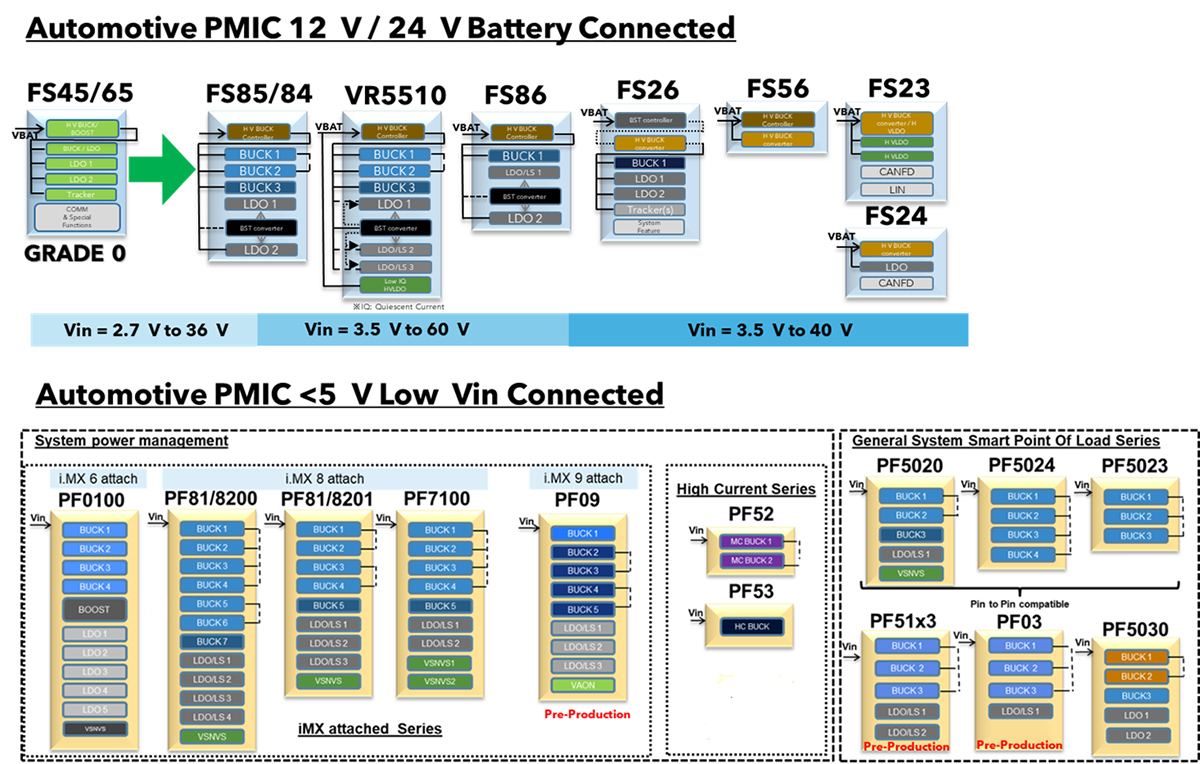
Figure 4: NXP Automotive PMIC Series
NXP’s automotive PMICs are divided into two series:high-voltage PMICs that can be directly connected to 12V/24V vehicle batteries (top of Figure 4), andlow-voltage PMICs that operate with input voltages below 5V (bottom of Figure 4).
Automotive PMICs integrate multiple voltage regulators, watchdog functions, voltage monitoring, and safety functions (compatible with functional safety levels QM to ASIL D) on a single chip, simplifying POWER SUPPLIES system, improving power efficiency, and reducing development time, BOM (number of components), and board space.
- [NXP Official] Power Management IC (PMIC) and System Basis Chip (SBC)
Three Key Features of NXP’s Automotive PMICs
This section introduces three key features of NXP’s automotive PMICs.
1. Power System Optimization
2. Accelerating Platform Development
3. High-Performance Power Delivery
1. Power System Optimization
NXP’s automotive PMICs streamline power system design, reducing development costs, BOM expenses, and board space requirements.
- Equipped with multi-channel power supplies
Buck converters, boost converters, LDOs (low dropout regulators), voltage trackers, and reference power sources.
- Easy configuration changes via OTP
Even when specifications change unexpectedly, OTP* allows quick adjustments to output voltage levels, power sequencing, and safety feature settings.
- OTP (One-Time Programmable) memory is a type of non-volatile ROM that allows data to be written only once and stores initial configuration settings for the device.

Figure 5: Power Sequence Programmable via OTP
- No need to develop a monitoring MCU
With built-in high-precision voltage monitoring and safety functions, there is no need to develop a separate monitoring MCU or its software.
- Integrated voltage monitoring and safety functions
When faults such as OV/UV (Over Voltage / Under Voltage), BIST (Built-in Self-Test), or watchdog errors exceed a defined threshold, the system automatically transitions to a safe state.
2. Facilitating Platform Development
NXP’s automotive PMICs offer high scalability, enabling maximum reuse of design assets and accelerating platform development.
- Multiple PMICs can be combined to operate as a single unit
Buck converters, boost converters, LDOs (low dropout regulators), voltage trackers, and reference power sources.
- Easy configuration changes via OTP
NXP’s automotive PMICs are designed based on the BYLink concept, featuring interconnectable pins and interface compatibility. This allows multiple PMICs to operate as a unified system. BYLink-enabled devices use dedicated terminals to easily synchronize power sequences across PMICs, with each sequence programmable via OTP. A wide range of high-voltage and low-voltage PMIC combinations supports various applications and processor power requirements.
- BYLink: A technology that enables synchronization of power sequences among multiple PIMCs through interconnectable pins and software compatibility. The next chapter will provide a detailed explanation of BYLink with specific examples.

Figure 6: Power system solution combining multiple PMICs.
- Can be attached as a power source for NXP and other microcontrollers.
NXP's automotive PMICs are 100% attachable to NXP microcontrollers/processors and compatible with many others.

Figure 7: NXP's automotive PMICs fully attach to NXP microcontrollers.
- Maximizes design asset reuse.
The automotive PMIC series adopts a common hardware and software interface, streamlining platform design.
3. High-performance power capabilities.
- Improved response to output voltage changes with wide bandwidth.
- Reduced current consumption in standby mode with ultra-low power.
- Reduced PCB size and BOM costs.
Automotive PMICs enabling functional safety design.
NXP's automotive PMICs incorporate safety features that enable compliance with the ISO26262 functional safety standards required in vehicles.
An overview of safety features will be explained using a system equipped with NXP's automotive PMIC and safety MCU (Figure 8).
The PMIC supplies power to the MCU core through the Vcore regulator, to the analog power via the VCCA regulator, and to external ICs (sensors) through the VAUX regulator. The PMIC and MCU are connected via SPI communication, with RSTB connected to the MCU's reset pin. In the event of a system failure, the safety switch, which transitions the system to a safe state, can be controlled by both the PMIC and the safety MCU.

Figure 8: NXP's automotive PMICs are equipped with safety features that support functional safety design.
Here are four features of the safety functions in NXP's automotive PMICs.
(The feature numbers (1) to (4) correspond to those in Figure 8.)
(1) Independent fail-safe state machine
- The fail-safe state machine is physically and electrically independent from other systems.
- Contains a voltage monitoring unit with configurable UV/OV thresholds.
- Includes analog and logic built-in self-test (ABIST/LBIST) for detecting latent faults.
(2) Watchdog
- The fail-safe state machine is physically and electrically independent from other systems.
- The watchdog (WD) function monitors the MCU for failures, featuring timeout WD, window WD, or Q&A WD.
(3) Multipurpose IO
- Multipurpose IO can be configured for wake-up input, FCCU monitoring*, and external IC error monitoring.
(4) Fail-safe output driver
- RSTB is connected to the MCU's hardware reset pin, allowing monitoring of reset events and assertion of the reset signal.
- Fail-safe pins (FS0B and/or FS1B) allow for a delayed operation timing of one of the fail-safe pins during a system failure, enabling a gradual transition of the system to a safe state.
Improving power development efficiency with the BYLink system.
To support applications such as vehicle electrification, ADAS, zones, and domain controllers, there is a trend towards higher performance and increased complexity in the power configurations of automotive ECUs. As a result, automotive ECU power development platforms require scalability to flexibly accommodate different power configurations for each application.
NXP's automotive PMICs are designed with the BYLink concept. PMICs equipped with interconnectable pins and software compatibility work together to safely and efficiently control power rails composed of multiple PMICs. Through BYLink, safety functions and power sequences among multiple PMICs are synchronized, allowing them to operate as if they were a single PMIC. The BYLink system optimizes power consumption management, integrates functional safety, and manages complex power sequences, thereby improving the efficiency of power platform development.
As an example of the BYLink configuration, let's examine the power system of an automotive ECU with a safety MCU. Figure 9 shows the evaluation board provided by NXP.
This is the block diagram of the BYLink Multiprocessor Demo Board (DEMO-BYL1-EVB). (The evaluation board includes only the left power circuit in Figure 9.)
Figure 9: Block diagram of the BYLink Demo Board (DEMO-BYL1-EVB).
This system includes one high-voltage PMIC for direct 12V/24V battery input, a safety MCU, a processor, and two low-voltage PMICs. The high-performance processor has high current consumption and uses DDR memory.
The safety MCU, with a functional safety level of ASIL D, is powered by the high-voltage PMIC FS8510, while the processor, with a functional safety level of ASIL B, is powered by the low-voltage PMICs PF5024 and PF5020. The PF5024 and PF5020 receive power from the high-voltage Buck (VPRE) of the FS8510, and their power-up timing is controlled by the GPIO of the safety MCU. The PF5024 and PF5020 are interconnected via the XFAILB pin, allowing synchronization of the power sequence. The FS8510 communicates with the safety MCU via SPI, while the compatible PF5024 and PF5020 communicate with the processor over a common I2C line.
This configuration is just one example. Other arrangements, such as separating low-voltage PMICs for the processor and peripherals (left side of Figure 10) or using four low-voltage PMICs for the processor (right side), can also be easily coordinated using BYLink to connect multiple PMICs.

Figure 10: Components of Power Management.
- Source: BYLink System Power Platform.
NXP's automotive PMICs compatible with BYLink allow flexible selection of power configurations based on the application, including high-voltage PMICs, the number and types of low-voltage PMICs, and ASIL levels. BYLink enables safe and scalable power design.
- [NXP Official] BYLink System Power Platform.
- [NXP Official] BYLink System Power Platform.
- In the next section, we will explain the features of NXP's automotive PMIC portfolio and key products.
Page 1: Basics of PMICs and Features of NXP's Automotive PMICs.
Related Info
NXP Tech Blog
Inquiry
Related Product Information
Introducing NXP's CAN TRANSCEIVER products with signal improvement (SIC)
NXP's SIC-equipped CAN TRANSCEIVER actively suppresses ringing on the transmitting side, stabilizing high-speed CANFD communications. It is software and pin compatible, allowing it to be replaced with existing designs, and is compliant with automotive standards.
- NXP Semiconductors NV
- NEXT Mobility

Introducing NXP's automotive LED DRIVER
Introducing NXP's automotive LED DRIVER. This product line supports constant voltage, constant current, high-precision PWM, and I2C/SPI, making it ideal for dimming multiple LEDs and displays.
- NXP Semiconductors NV
- NEXT Mobility

A thorough explanation of the appeal of NXP's automotive PMICs (Page 2/2) | An explanation of NXP's automotive PMIC portfolio and the features of its representative products.
This article explains the necessity of PMICs in automotive ECUs, as well as the features, advantages, and portfolio of NXP's automotive PMICs. This first part focuses on the automotive PMIC portfolio and the characteristics of its representative products.
- NXP Semiconductors NV
- NEXT Mobility
An In-Depth Look at the Advantages of NXP's Automotive Microcontroller S32K1
NXP's S32K1 series of automotive microcontrollers incorporates the ARM Cortex-M0+ and M4F cores, achieving high processing power and low power consumption. We will thoroughly explain its appeal and features.
- NXP Semiconductors NV
- NEXT Mobility
Introduction to NXP's Automotive General-Purpose Microcontroller Products
NXP’s general-purpose automotive microcontrollers—S32K1, S12 MagniV, and S32K3 families—combine high performance, security, and cost efficiency to support the advancement of automotive technologies.
- NXP Semiconductors NV
- NEXT Mobility
NXP Automotive Microcontroller S32K311 Evaluation Board by NEXTY Electronics
The S32K311 is NXP's latest automotive microcontroller, offering high performance in a small package and the latest features at a low cost. We will introduce its features and our own S32K evaluation board.
- NXP Semiconductors NV
- NEXT Mobility
Link to Related Technical Columns

Real-time AI tracking camera built with i.MX 93 - Achieving human tracking with NPU and servo motors
This document explains the procedure for building a camera that uses the i.MX 93 NPU and eIQ to perform face detection and track people in real time, from building a Yocto BSP to configuring PWM and using servo control.
No need for an oscilloscope! High-precision time measurement using ARM-Cortex M DWT CYCCNT - A practical guide to minimized steps
This article provides an easy-to-understand explanation of the procedures and practical points for highly accurate time measurement on ARM Cortex-M using DWT CYCCNT without the need for external equipment.

A thorough explanation of the directories generated by bitbake | Essential for troubleshooting Yocto development
We will explain the structure and use of bitbake's tmp subdirectories (work, work-shared, deploy, etc.), as well as Yocto troubleshooting procedures using log checking and deb distribution.

Azure RTOS ThreadX Practical Guide: Practical Explanation of Task Management and Communication Functions
We will explain multitasking design and communication functions such as message queues in Azure RTOS (ThreadX).
First Steps with Azure RTOS: Creating a "Hello World" Project Using Azure RTOS
This article explains how to create, build, and debug a Hello World message using Azure RTOS (ThreadX) on the i.MX RT1170 evaluation board.
Building an i.MX Development Environment (Yocto Edition) | Technical Column
This article explains how to set up a Yocto development environment using NXP’s i.MX series. It covers hardware, preparation steps, and build procedures, helping you prepare to flash images on i.MX evaluation boards.