Load-driven MOS FETS with external protection offer opportunities for cost optimization, but they are also prone to overlooking abnormal conditions such as overcurrent, overheating, short circuits, and inductive surges during design. This is where Intelligent Power Devices (IPDs), which integrate SWITCHES elements with protection and diagnostics, come in handy. This article will begin by explaining the differences between High Side Drivers (HSDs) and Low Side Drivers (LSDs), which are often confusing in the field, and summarize the key points of selection, thermal management, and diagnostics in a way that can be translated into design decisions.
Click here for the basics column on IPD:
What is an IPD (Intelligent Power Device)? The mechanism and benefits of semiconductor SWITCHES attracting attention in automotive and industrial equipment.
Let's clarify the differences between HSD and LSD.
Both HSD and LSD are SWITCHES for turning a load ON/OFF, but the crucial difference lies in "which side of POWER SUPPLIES they switch off." HSD SWITCHES POWER SUPPLIES (VCC/VBAT) side, while LSD SWITCHES the ground (GND) side. It's helpful to understand that POWER SUPPLIES side refers to the positive side of the battery or DC POWER SUPPLIES, and GND refers to the 0V reference side.
This difference is significant because it's not simply a matter of wiring, but directly relates to whether the load can be disconnected from the POWER SUPPLIES supply when switched off, and how easily abnormalities such as disconnections and short circuits can be detected. If safety design and diagnostic capabilities are prioritized, HSD tends to be advantageous, while LSD is a more practical choice if you want to simplify the configuration and leverage existing design assets.
| Item | HSD (High Side Driver) | LSD (Low Side Driver) |
|---|---|---|
| SWITCHES position | POWER SUPPLIES (VCC) side | Ground (GND) side |
| Load connection | Between SWITCHES and GND | Between VCC and SWITCHES |
| Basic operation | When ON, VCC is supplied to the load. | When ON, connect the load to GND. |
| Main uses | Onboard POWER SUPPLIES, lamps, heater operation | General-purpose SWITCHES, motor control, LED |
Comparison of HSD and LSD

HSD Configuration Diagram

LSD Configuration Diagram
HSD characteristics
- Connection method: By placing SWITCHES between POWER SUPPLIES and the load and fixing the ground side of the load, stable operation is achieved.
-
Merit:
o Because the GND side of the load is fixed, disconnections and abnormalities are easily detected, resulting in high diagnostic capability.
o Safety is improved because the load can be completely disconnected from POWER SUPPLIES when the device is turned off.
POWER SUPPLIES supply control allows for a design that is less susceptible to noise. -
Points to note:
Because SWITCHES occurs on the high-voltage side, the driver circuit tends to become complex, requiring advanced design skills.
HSD has a configuration that makes it easy to fix the load's GND side to 0V reference by placing SWITCHES between POWER SUPPLIES and the load. When the load side reference is aligned, it becomes easier to assemble a design that estimates the state by observing the potential of the load TERMINALS, and it becomes easier to incorporate LOGIC for detecting disconnections and abnormalities.
Another major advantage of HSD is that it makes it easy to disconnect the load from POWER SUPPLIES when it is turned off. This makes it easier to handle in cases where you want to prevent unintended energization or false illumination, enhance safety during maintenance, or transition to a safe mode in the event of an abnormality. Furthermore, it is compatible with methods that determine TERMINALS potential by flowing a small diagnostic current when it is turned off, and tends to enhance the diagnostic capabilities of the system (the diagnostic methods that can be implemented depend on the device specifications).
On the other hand, since HSDs are high-side SWITCHES, the gate drive and protection circuits tend to be more complex in general. However, when using IPDs, many of these "high-side-specific troubles" are absorbed within the device itself, and the responsibility of external circuits is reduced, which is an advantage of adopting them. That being said, the behavior of EMI and temperature rise varies depending on POWER SUPPLIES line surges and mounting conditions, so it is important to verify under consistent evaluation conditions.
-
Example of use with car headlights
If SWITCHES is set to the Low position, and the wiring comes into contact with the body, the circuit will be established without going through SWITCHES, which can result in the lights not being able to be turned off (runaway state) or an increased risk of fire due to overcurrent.
By placing SWITCHES on the High side, even if the wiring between the load and SWITCHES is damaged and comes into contact with the body (ground) (ground fault), the IPD can detect the overcurrent abnormality and shut off immediately.

Characteristics of LSD
-
Connection method: SWITCHES is placed between the load and ground, resulting in a simple and low-cost control circuit design.
-
Merit:
The control circuit is simple and low cost.
The driver circuit is easy to design and suitable for mass production. -
Points to note:
Even when the power is off, the load remains connected to POWER SUPPLIES, which can make diagnosing a broken wire difficult.
The potential on the load side is prone to fluctuations, which may necessitate noise countermeasures.
LSDs (Limited Slip Differentials) use a configuration that places SWITCHES between the load and ground, making it easier to handle control signals relative to 0V and simplifying the design of the drive circuit. Therefore, it is a popular choice when you want to leverage existing design assets that assume ground-side SWITCHES, or when you want to simplify the configuration to prioritize cost and startup speed.
One point to note is that with an LSD, even when it's OFF, a load tends to remain on POWER SUPPLIES side, and the potential of the load TERMINALS can change depending on the circuit conditions. Therefore, when diagnosing a broken wire, it's crucial to decide early on which method to use (TERMINALS voltage monitoring, applying a diagnostic current, or using a separate diagnostic wire) to avoid rework in later stages.
Furthermore, SWITCHES the GND side means that the load's return current changes with SWITCHES, and the GND reference may fluctuate through the wiring INDUCTORS. When high-current loops and signal GNDs are routed close together, the risk of the control system malfunctioning due to noise increases. The more an LSD is used, the more important it becomes to have a layout that takes current paths and reference points into consideration (a design that "visualizes" and separates the flow of return current).
-
Example of use with series-connected LEDs
High-side LEDs require high voltage to drive, but because this LED is on the low-side, it can be driven at a lower voltage (resulting in a simpler and cheaper internal configuration). Also, LEDs are often driven with constant current, and because the measurement can be taken very close to the reference GND, high-precision control becomes possible.
There are devices that integrate multiple LSDs into a single package, and using them makes it possible to significantly simplify the wiring layout on a circuit board.

Checkpoints for selecting an IPD (Individual Planner)
Selecting an IPD (Inductive Processing Unit) based solely on "ratings" such as continuous current and voltage rating can lead to problems with surge handling for inductive loads, mounting thermal resistance, and routing of diagnostic outputs. Here, we will organize the key points for selection.
The necessity and selection of protective features
When selecting an IPD (Integrated Power Distribution Unit), consider the necessary protection functions based on the operating environment and load characteristics. For example, overtemperature protection and overcurrent protection are essential in most applications, but the importance of reverse polarity protection and active clamping varies depending on the specific load and system configuration.
In systems where misconnections are a real possibility, such as automotive applications, reverse polarity protection (a mechanism to prevent damage when the +/- terminals of POWER SUPPLIES are connected incorrectly) is often a requirement. When interrupting inductive loads (motors and solenoids), overvoltage due to back electromotive force is likely to occur, and this is where active clamping comes in handy. Active clamping controls and dissipates the overvoltage during interruption at the element side, affecting both the energy handling of the load and EMI. The key is to determine which protection is needed for which load by working backward from the load type and abnormal scenario.
Checking voltage and current ratings
It is important to select an IPD (Integrated Power Distribution) with sufficient margin for the maximum current and voltage of the load. Using it beyond its rating will shorten the lifespan of the device. Lamps and motors have inrush current when starting up, and with PWM (Pulse Width Modulation) drive, the effective current and losses will differ. With inductive loads, the element receives energy through clamping action when the circuit is interrupted, so it is necessary to check that the overall operating conditions are not unreasonable, not just the simple continuous current rating.
The aim of having a margin in the ratings isn't just to "prevent damage." When temperature rise is suppressed, the risk of protection activating unintentionally is reduced, and diagnostic judgment conditions become more stable. As a result, it leads to a design that is more resilient to variations in mass production and environmental fluctuations.
Thermal design and heat dissipation measures
Thermal design and heat dissipation are crucial factors affecting the reliability of IPDs (Integrated Devices). Because IPDs SWITCHES high currents at high speeds, the heat generated internally must be efficiently dissipated. Insufficient heat dissipation can cause the device temperature to rise, leading to performance degradation, shortened lifespan, and in the worst case, failure.
The following points are important for heat dissipation:
-
1. Heatsink design and installation:
Select a heatsink suitable for the IPD package and ensure reliable contact to dissipate heat. Using thermal conductive grease or pads with high thermal conductivity is also effective.
-
2. Design innovations for circuit boards:
Expanding the heat dissipation pattern and utilizing multilayer substrates are required to design the circuit to dissipate heat throughout the entire substrate. Increasing the thickness and area of the copper foil also contributes to reducing thermal resistance.
-
3. Air cooling/forced cooling:
Fans and air cooling systems are installed as needed to circulate the surrounding air and efficiently remove heat.
-
4. Utilization of TEMPERATURE SENSORS:
By placing TEMPERATURE SENSORS inside the IPD or on the circuit board and monitoring the temperature in real time, it is possible to detect overheating conditions early and take countermeasures.
-
5. Ensuring design margins:
Designing the device with sufficient margin in rated current and voltage to suppress heat generation during overload or malfunctions leads to improved reliability.
These heat dissipation measures are fundamental to the long-term stable operation of IPDs and are essential, especially in harsh environments such as automotive and industrial applications. It is recommended to perform optimal heat dissipation design through thermal analysis and testing during the design phase.
Control interface compatibility
Ensure that the interface with the microcontroller and control circuit is compatible, and pay attention to signal levels and driving methods. For example, design must conform to the specifications of PWM control and digital inputs.
Especially when controlling an IPD with a microcontroller, it's not simply a matter of "ON when the input is High/Low." It's crucial to check the input threshold, input logic, PWM frequency tolerance, and how the output behaves in case of a fault (automatic recovery or latching). While PWM allows for adjustment of average power, losses and EMI change depending on the frequency and rise characteristics, so control conditions and device specifications must be determined together. If this is unclear, more absorption will be done on the software side than on the circuit side, leading to an unstable design.
Utilization of diagnostic functions
By utilizing the self-diagnostic output, it becomes possible to detect anomalies and perform preventative maintenance across the entire system, contributing to a reduction in downtime.
To achieve this, a design is required that monitors diagnostic signals with a microcontroller and takes appropriate action in the event of an anomaly. Diagnostic outputs may indicate the status with a single status signal, or they may return information linked to the load current. Since different methods require different designs for pull-up resistors, FILTERS, and interrupt handling, it is important to proceed with circuit design and software design simultaneously.
Future Outlook: Further Value Enhancement of IPD
IPDs are widely used in applications ranging from automotive to industrial use, but in the future, not only will the load current increase with electrification, but control based on diagnostic information will also become commonplace. Rather than simply detecting an anomaly and stopping, design requirements will shift towards derating (control that gradually reduces output to protect) according to temperature and load conditions, and protecting without stopping, so that diagnostic interfaces and protection behavior will become central to device selection. In this trend, the position of IPDs will change from "SWITCHES" to "part of control and diagnostics," and the importance of their selection is expected to increase even further.
Summary
IPDs are high-performance semiconductors that integrate power SWITCHES, control circuits, and protection functions, and are widely used in applications ranging from automotive to industrial uses. The choice between HSDs and LSDs directly impacts the application, safety, and ease of design, and requires careful consideration during system design.
Furthermore, by paying attention to design points such as the selection of protection functions, thermal design, and the utilization of diagnostic functions, it becomes possible to build safer and more reliable systems. IPDs are semiconductor devices that will become increasingly important as IoT and electrification advance in the future.
If you are interested, please feel free Inquiry Nexty Electronics.
Related Info
What is an IPD (Intelligent Power Device)? The mechanism and benefits of semiconductor SWITCHES attracting attention in automotive and industrial equipmentInquiry
Link to Related Technical Columns
Related Product Information
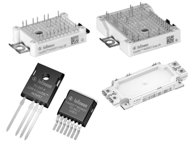
High-side/low-side SWITCHES Replaces relays and FUSES- Automotive-quality smart SWITCHES for smarter and safer power distribution and load control.
These high-side and low-side automotive smart SWITCHES are equipped with protection and diagnostic functions for overcurrent and overtemperature, enabling safe and reliable load control.
- Infineon Technologies AG
- NEXT Mobility

車載向け高速伝送技術GMSL2の特徴と製品ラインナップについて
より高画素なカメラの映像データを扱うことができるアナログ・デバイセズの次世代GMSL、GMSL2について特徴を説明します。
- Analog Devices, Inc.
- NEXT Mobility
- ICT and Industrial
Solutions for low, medium and high power motor drives
The motor speed is controlled by varying the frequency and voltage of the motor signal, with power ranging from a few hundred watts to a megawatt.
- Infineon Technologies AG
- ICT and Industrial
- Smart Factories and Robotics

Gate Driver Infineon's gate drivers deliver high efficiency and reliability, accelerating the next generation of power electronics.
Infineon's gate drivers control high-power devices with high precision and safety, and their high insulation voltage and diverse functions support reliability in automotive and industrial applications.
- Infineon Technologies AG
- NEXT Mobility
- ICT and Industrial
Motion Controllers and Motor Drivers for Stepping Motors
Our industry-leading motion control products improve energy efficiency, prevent loss of synchronization, and reduce motor noise and vibration, making them ideal for fields requiring advanced control.
- Analog Devices, Inc.
- NEXT Mobility
- ICT and Industrial
CoolSET™ AC-DC Integrated Power IC High efficiency AC-DC POWER SUPPLIES IC integrating a PWM controller and high voltage MOS FETS. Compact, highly reliable, and simplifies SMPS design.
This highly efficient IC for AC-DC POWER SUPPLIES integrates a PWM controller and high-voltage MOS FETS, simplifying design and improving reliability.
- Infineon Technologies AG
- ICT and Industrial
- Smart Factories and Robotics