
- NXP Semiconductors NV
- NEXT Mobility
CAN FD communication, which is currently the mainstream in-vehicle network, is a communication specification that extends the conventional CAN communication.
CAN FD communication enables the transmission and reception of large amounts of data at high speeds compared to conventional CAN communication, but this can cause signal ringing on the bus communication line, which can lead to communication malfunctions.
The solution to this problem is SIC (Signal Improvement Capability), which is defined in CiA601-4.
→ CiA601-4 has been unified with the release of the new ISO11898-2:2024 standard and is currently in use.
This page explains NXP's CAN TRANSCEIVER products equipped with signal improvement function (SIC), which improves the ringing that occurs when CAN is communicated at high speeds, enabling stable high-speed communication.
CAN FD Trade-Offs (Topology vs. Data Rate)
CAN networks are cost-effective, robust, scalable, easy to implement and capable of supporting complex topologies throughout the vehicle.
However, as new features are added to cars, the need for more data exchange exceeds the limits of CAN networking systems. CAN FD communication was born to address this situation, and is a technology that supports higher bandwidth than traditional CAN communication, increasing data rates from 500 Kbps to a maximum of 5 Mbps.
CAN FD uses a bus-type network topology (wiring structure) and can configure a network by connecting each node (ECU) to the communication line, which has the advantage of making the network simple and easy to design.
- Linear method
To achieve high-speed communication on a CAN bus with stubs (branches), one method is to connect using a linear topology (daisy chain), but there are concerns about increased cost and weight due to the increased harnesses.
- Multi-stub method
A multi-stub connection with multiple branches can reduce the amount of wiring required, but it can cause interference from signal reflections known as "signal ringing," which can degrade the signal quality of the CAN bus.
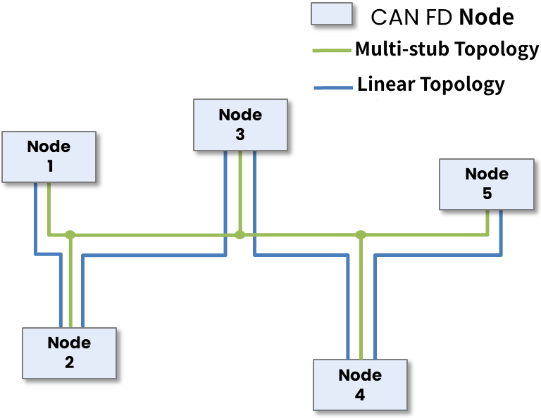
CAN bus network
The following diagram shows an image of signal ringing.
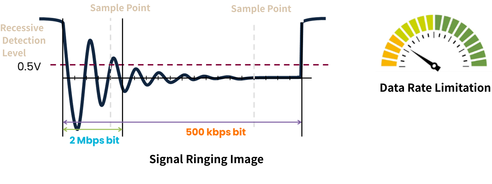
In CAN FD, the 1-bit length is short, which means that the time until the sample point is reduced, and the ringing convergence time, which was not an issue with conventional CAN communication, becomes an issue.
This signal ringing effectively limits CAN FD communication to 2Mbps in many networks and restricts its use to more linear topologies.
As a result, wiring harnesses must avoid branching with long CABLES, which increases the complexity of routing the harness throughout the vehicle, resulting in increased cost and weight.
Details of SIC technology
Here we explain how NXP's SIC CAN TRANSCEIVER suppresses signal ringing.
SIC signal quality improvement functions include those that improve on the transmitting side (TX method) and those that improve on the receiving side (RX method), and NXP transceivers improve on the transmitting side. This is because the transmitting side has a standard, the TXD signal from the microcontroller, and it is thought to be superior to performing signal processing on the signal (which may include noise, etc.) transmitted over the bus. The old CiA standard included both the TX method and the RX method, but the latest standard, ISO11898-2:2024, only includes the TX method.
Active low-impedance drive of recessive edges by TXD input signal
The SIC does not immediately switch the impedance from low to high after the dominant-recessive edge, but instead maintains an intermediate impedance range (75-125 ohms). Also, the maximum delay measured from the TXD recessive is 530 nSec.
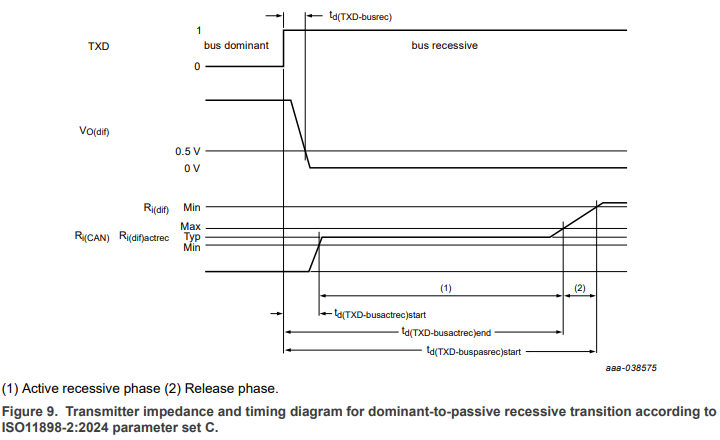
Excerpt from TJA1462 datasheet
In this way, NXP's SIC technology actively improves the CAN signal, eliminating signal integrity issues caused by ringing.
SIC waveform observation
I would like to confirm the actual effect of SIC using a system demo board equipped with multiple NXP CAN TRANSCEIVER.
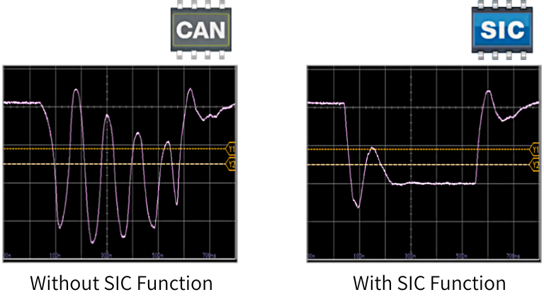
This time, we used the TJA1043 (without SIC) and the TJA1465A (with SIC and partial networking) to observe the bus recessive waveforms output by each. The communication speed during waveform observation was 2Mbps.
Without SIC, large ringing occurs on the bus line, exceeding the recessive confirmation level of 0.5V.
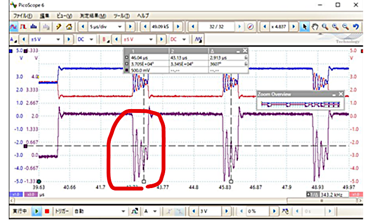
TJA1043 (without SIC)
Next, we stopped the output of the TJA1043 and similarly observed the bus waveform output by the TJA1465A.
The SIC effect keeps the ringing level below 0.5V, so there is no chance of it being mistaken for a dominant.
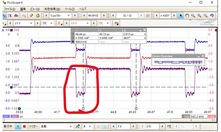
TJA1465A (with SIC)
TJA146x Product Overview
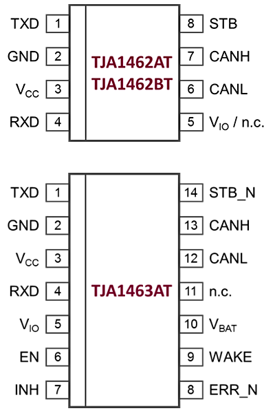
This is a product overview of NXP's SIC CAN TRANSCEIVER TJA146x.
- CAN FD SIC products are pin-compatible and can be directly substituted for standard 8-pin and 14-pin CAN TRANSCEIVER.
- Compatible with ISO11898-2:2016 and SAE J2284-x (WUP filter twake = 0.5μs to 1.8μs)
- No software changes are required (SW driver compatibility from TJA1043 to TJA1463)
- AEC-Q100 Grade-0 compliant product (TJR146x)
Summary
So far, we have explained NXP's in-vehicle network product, CAN TRANSCEIVER with signal improvement function (SIC).
NXP's wide-ranging lineup of in-vehicle network products meets a variety of customer requirements, so if you're interested, please Inquiry Nexty Electronics.
Related Info
INV product related links
[Product Information] CAN TRANSCEIVER
Introducing the full-size CAN TRANSCEIVER from NXP's industry-leading IVN products.
[Product Information] CAN SIC products
Introducing the full-size CAN TRANSCEIVER from NXP's industry-leading IVN products.
NXP Tech Blog
Inquiry
Related Product Information

Introducing NXP's automotive LED DRIVER
Introducing NXP's automotive LED DRIVER. This product line supports constant voltage, constant current, high-precision PWM, and I2C/SPI, making it ideal for dimming multiple LEDs and displays.
- NXP Semiconductors NV
- NEXT Mobility

A thorough explanation of the appeal of NXP's automotive PMICs (Page 2/2) | An explanation of NXP's automotive PMIC portfolio and the features of its representative products.
This article explains the necessity of PMICs in automotive ECUs, as well as the features, advantages, and portfolio of NXP's automotive PMICs. This first part focuses on the automotive PMIC portfolio and the characteristics of its representative products.
- NXP Semiconductors NV
- NEXT Mobility
In-Depth Guide to NXP's Automotive PMICs (Page 1/2): Fundamentals and Key Features
This article explains the importance of PMICs in automotive ECUs and introduces the features, advantages, and portfolio of NXP’s automotive PMICs. It covers the basics of PMICs and highlights NXP’s offerings.
- NXP Semiconductors NV
- NEXT Mobility

An In-Depth Look at the Advantages of NXP's Automotive Microcontroller S32K1
NXP's S32K1 series of automotive microcontrollers incorporates the ARM Cortex-M0+ and M4F cores, achieving high processing power and low power consumption. We will thoroughly explain its appeal and features.
- NXP Semiconductors NV
- NEXT Mobility

Introduction to NXP's Automotive General-Purpose Microcontroller Products
NXP’s general-purpose automotive microcontrollers—S32K1, S12 MagniV, and S32K3 families—combine high performance, security, and cost efficiency to support the advancement of automotive technologies.
- NXP Semiconductors NV
- NEXT Mobility

NXP Automotive Microcontroller S32K311 Evaluation Board by NEXTY Electronics
The S32K311 is NXP's latest automotive microcontroller, offering high performance in a small package and the latest features at a low cost. We will introduce its features and our own S32K evaluation board.
- NXP Semiconductors NV
- NEXT Mobility
Link to Related Technical Columns

Real-time AI tracking camera built with i.MX 93 - Achieving human tracking with NPU and servo motors
This document explains the procedure for building a camera that uses the i.MX 93 NPU and eIQ to perform face detection and track people in real time, from building a Yocto BSP to configuring PWM and using servo control.

No need for an oscilloscope! High-precision time measurement using ARM-Cortex M DWT CYCCNT - A practical guide to minimized steps
This article provides an easy-to-understand explanation of the procedures and practical points for highly accurate time measurement on ARM Cortex-M using DWT CYCCNT without the need for external equipment.

A thorough explanation of the directories generated by bitbake | Essential for troubleshooting Yocto development
We will explain the structure and use of bitbake's tmp subdirectories (work, work-shared, deploy, etc.), as well as Yocto troubleshooting procedures using log checking and deb distribution.

Azure RTOS ThreadX Practical Guide: Practical Explanation of Task Management and Communication Functions
We will explain multitasking design and communication functions such as message queues in Azure RTOS (ThreadX).
First Steps with Azure RTOS: Creating a "Hello World" Project Using Azure RTOS
This article explains how to create, build, and debug a Hello World message using Azure RTOS (ThreadX) on the i.MX RT1170 evaluation board.

Building an i.MX Development Environment (Yocto Edition) | Technical Column
This article explains how to set up a Yocto development environment using NXP’s i.MX series. It covers hardware, preparation steps, and build procedures, helping you prepare to flash images on i.MX evaluation boards.