1. Introduction
Hello! I'm a member of the Development Department at Nexty Electronics.
We at Nexty Electronics are responsible for providing technical support for various edge AI devices.
This column will showcase a demonstration of a person tracking camera using NXP's i.MX 93.
1-1. Benefits of Edge AI and Features of i.MX 93
In recent years, edge AI, which does not rely on the cloud, has been attracting attention. Its real-time capabilities due to the elimination of network latency, low power consumption due to reduced communication data, and privacy protection by not transmitting personal information externally are of great value in smart devices and industrial equipment.
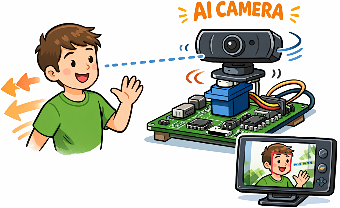
In this column, we will introduce a demonstration of a camera that detects human faces and tracks them using a servo motor, as a concrete example that takes advantage of these benefits.
The core of this demo is NXP's i.MX 93.
The i.MX 93 features a Neural Processing Unit (NPU) with a maximum computing performance of 0.5 TOPS, enabling efficient execution of AI models such as TensorFlow Lite and ONNX.
The CPU features a hybrid configuration combining an Arm Cortex-A55 and a Cortex-M33, which is suitable for real-time control, enabling stable simultaneous image processing and motor control. Furthermore, it is equipped with a wealth of peripherals such as PWM and I²C, making it an ideal platform for building systems that integrate AI inference and device control.
The following explains, step by step, how to run a face detection model, control servo motors, and build a person-tracking camera using the FRDM i.MX 93 development board.
Because everything from AI inference to motor control is completed on a single edge device, there is no latency due to cloud communication, resulting in low power consumption and high real-time performance.
We encourage you to experience the potential of the i.MX 93 through this demo.
1-2. System Configuration
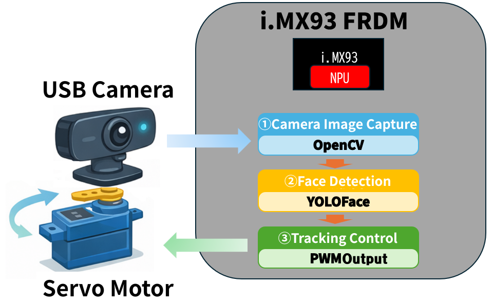
The system captures video from a USB camera using OpenCV and performs real-time face detection on the NPU.
The system selects the largest face detected on the screen (i.e., the closest person) as the target for tracking.
If the position of the person being tracked shifts away from the center of the screen, the servo motor is driven to automatically adjust the camera's orientation so that the person remains near the center of the screen at all times.
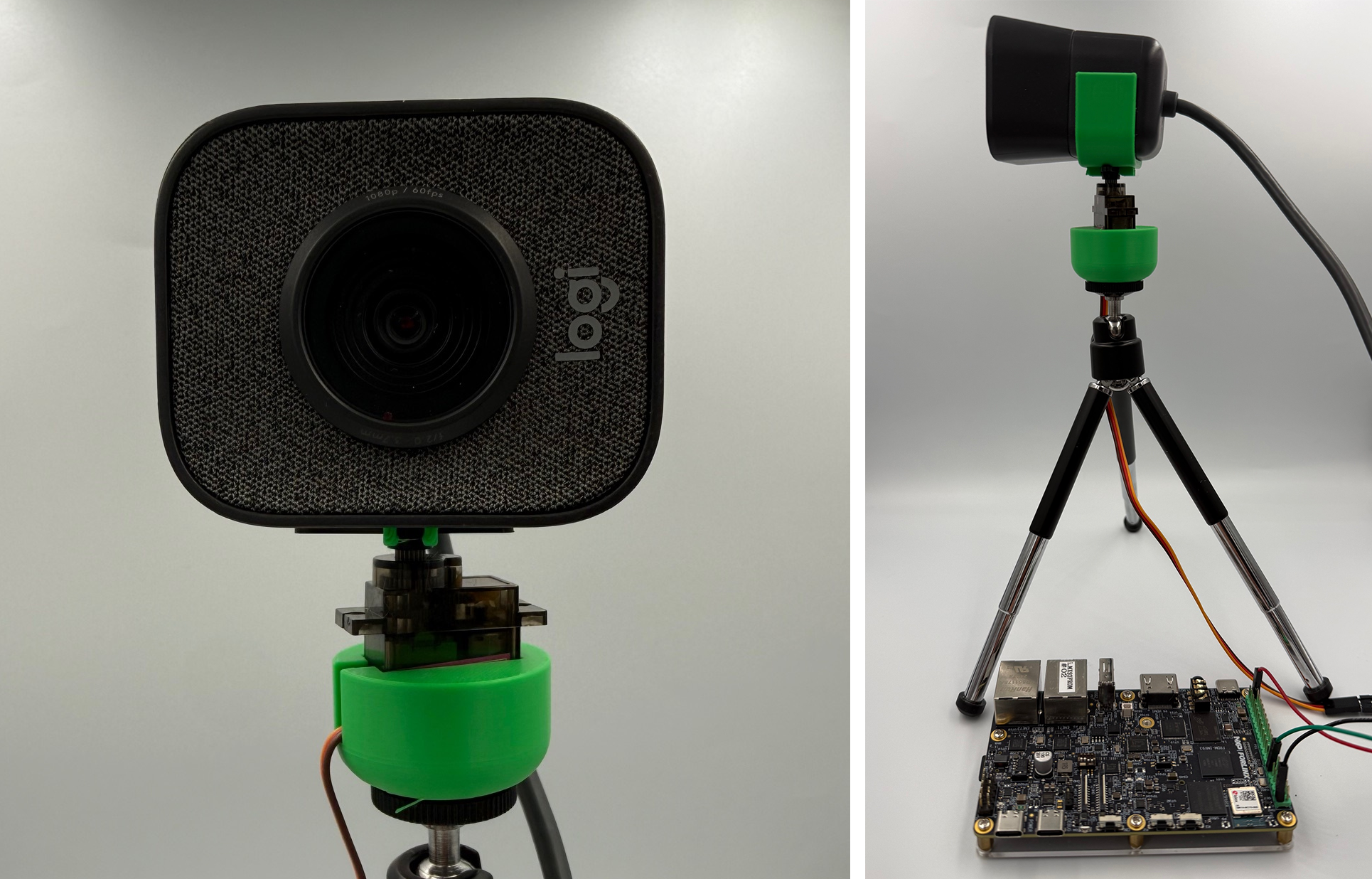
Here are close-ups of the camera section and overall photos of the demo unit.
1-3. Overview of i.MX 93NPU and eIQToolkit
One of the key features of the i.MX 93 is that it has an NPU (Neural Processing Unit) integrated into the SoC.
The i.MX 93 features an NPU with a maximum computing performance of 0.5 TOPS, enabling AI inference processing such as image recognition, object detection, and face detection without placing a heavy load on the CPU.
When performing AI inference using only a CPU, increased processing load and power consumption tend to be problematic, but by utilizing an NPU,
- Low-power AI inference
- Stable real-time processing
- It is possible to allocate CPU resources to other control processes.
You can gain the following benefits.
In this demo, face detection processing is performed on the NPU, while the CPU is responsible for video display and servo motor control.
NXP provides the eIQ Toolkit as an environment for handling AI models.
This software can convert and optimize models created with TensorFlow Lite or ONNX into a format that can be executed on NXP SoCs/microcontrollers such as the i.MX series.
This demo uses pre-built models, so we will omit the explanation of eIQ Toolkit. However, please refer to the eIQ Toolkit website for details.
2. About NXP Yocto Project BSP
The FRDM i.MX 93 development board is shipped with the NXP Yocto Project BSP (hereinafter referred to as BSP) pre-programmed onto the eMMC, but this time, the configuration needs to be changed in order to utilize the PWM function.
We have published a technical column titled "Building the i.MX Development Environment (Yocto Edition)" which details the BSP build procedure, so please refer to that as well.
Now let's proceed with building the BSP.
2-1. Recommended Host Environment
These are the recommended specifications for the PC used for building the project.
| Item | Requirements |
|---|---|
| OS | Ubuntu 20.04 and later |
| HDD | Minimum 50GB, recommended 250GB or more. |
| CPU core | Recommended 8 threads |
| Memory devices | 16GB or more recommended |
| USB | Equipped with one or more USB 2.0 or USB 3.0 ports. |
2-2. Build Procedure (Simplified Version)
This outlines the build process. Please see the reference links for further details.
1. First, install the commands required to build the BSP.
Open a terminal and execute the following. $ is the terminal prompt symbol.
$ sudo apt-get install gawk wget git-core diffstat unzip texinfo gcc-multilib \ build-essential chrpath socat cpio python python3 python3-pip python3-pexpect \ xz-utils debianutils iputils-ping python3-git python3-jinja2 libegl1-mesa libsdl1.2-dev \ pylint3 xterm rsync curl zstd lz4 libssl-dev2. Install the repo utility.
$ mkdir ~/bin
$ curl https://storage.googleapis.com/git-repo-downloads/repo > ~/bin/repo
$ chmod a+x ~/bin/repo
$ export PATH=~/bin:$PATH
3. Configure Git.
$ git config --global user.name "Your Name"
$ git config --global user.email "Your Email"
$ git config --list
4. Set up the BSP.
$ mkdir imx93-yocto
$ cd imx93-yocto
$ repo init -u https://github.com/nxp-imx/imx-manifest -b imx-linux-scarthgap -m imx-6.6.36-2.1.0.xml
$ repo sync
5. Integrate the layers for the FRDM i.MX 93 development board.
$ cd ./sources # imx93-yocto/sourcesに移動します
$ git clone https://github.com/nxp-imx-support/meta-imx-frdm.git
6. Execute the following command to build the BSP environment for the FRDM i.MX 93 development board.
$ MACHINE=imx93frdm DISTRO=fsl-imx-xwayland source sources/meta-imx-frdm/tools/imx-frdm-setup.sh -b frdm-imx937. Perform the build. Depending on your PC, this process may take several hours or more.
$ bitbake imx-image-full8. Once the build is complete, write the image to the SD card. Insert the SD card into the FRDM i.MX 93 development board and boot it up. Specify the path to the SD card to write to in /dev/sdX.
Please specify the wic.zst file in the directory as the image name.
$ zstdcat tmp/deploy/images/<image_name>.wic.zst | sudo dd of=/dev/sdX bs=4M status=progress conv=fsync2-3. Operation Check
Insert the SD card into the FRDM i.MX 93 development board. Connect KEY BOARD, mouse, and display, then POWER SUPPLIES on the board.
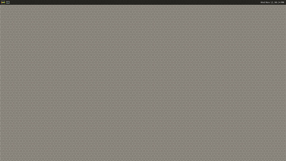
When BSP starts up, the following screen will be displayed.
3. Servo motor control
3-1. PWM Basics and Settings
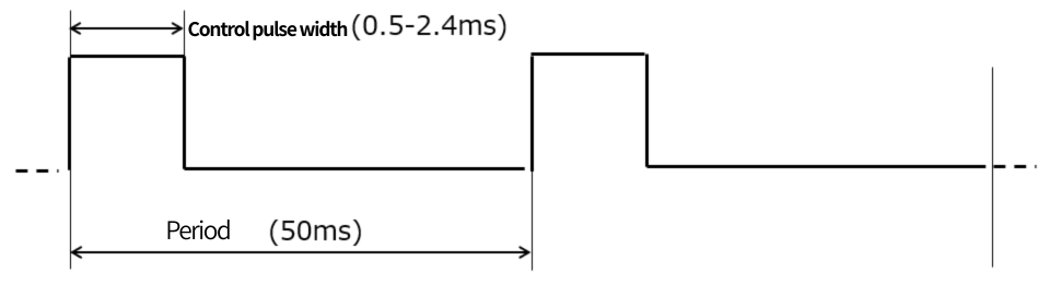
This system uses a hobby-grade servo motor called the MG90D. To drive this servo, the following pulse signal is required. The i.MX 93 has a peripheral called a TPM (Timer/PWM Module) that outputs a high-precision PWM signal, so we will use this for control.
After flashing the built BSP, the PWM signal output of the FRDM i.MX 93 development board will be connected to the RGB-LED on the board. Therefore, in order to control the servo motor, this output needs to be changed to a header pin.
Changing the PWM output pin in BSP requires steps such as adding and modifying layers during the build process, but this time we will simply change the PWM output pin by modifying the DTB file.
3-2. What is a DTB file?
A DTB file is an abbreviation for Device Tree Blob file. The Linux kernel needs to know the hardware configuration of the SoC it is running on when it boots up. This information is stored in binary format in a DTB file.
DTB files are converted from DTS (Device Tree Source) files, which are written in text. By modifying the hardware configuration information in the DTS file, it becomes possible to change the pin to which the PWM output is directed.
The specific steps are as follows:
3-3. Converting DTB files to DTS files
Read the SD card written in "2. About NXP Yocto Project BSP" on your host PC. You should see the /boot directory when you look at the mounted drive. Copy the imx93-11x11-frdm.dtb file in this directory to a suitable working directory on your host PC.
Since DTB files are in binary format, they need to be converted to source files in order to make modifications.
If dtc is not found on your host PC, please install it using the following command.
$ sudo apt update
$ sudo apt install device-tree-compiler
$ dtc --version
If the version number is displayed, then DTC is installed.
To convert a DTB file to a source file, execute the following command:
$ dtc -I dtb -O dts -o imx93-11x11-frdm.dts imx93-11x11-frdm.dtbIf the file imx93-11x11-frdm.dts is created in the directory, the process was successful.
3-4. Modify the DTS file to output the PWM signal to the header pin.
Next, we will modify this DTS file to change the output destination of the PWM signal.
Open imx93-11x11-frdm.dts with your preferred text editor.
Search for "pinctrl@443c0000" in your editor and add the following content inside the following "{}". The location within the {} is fine.
pinctrl@443c0000 {
  ....
+  tpm4grp {
+    fsl,pins = <0x24 0x1d4 0x00 0x01 0x00 0x19e>;
+	   phandle = <0x80>;
+  }
  ....
};
This configuration changes the settings of the i.MX 93-pin controller. Specifically, it configures the PWM signal to be output from GPIO_IO05.
Next, search for "pwm@424f0000" and add the following content inside the {} as before.
pwm@424f0000 {
+   pinctrl-0  = <0x80>;
}
This setting will reflect the output destination setting of the pin controller that you just configured to the PWM device (TPM4-CH0). In other words, the PWM signal generated by TPM4-CH0 will now be output from GPIO_IO05.
3-5. Updating the DTB file
Save the modified DTS file as imx93-11x11-frdm-pwm.dts. Convert it to a DTB file using the dtc command. Execute the following command:
$ dtc -I dts -O dtb -o imx93-11x11-frdm-pwm.dtb imx93-11x11-frdm-pwm.dtsWrite the converted imx93-11x11-frdm-pwm.dtb file to the /boot directory on your SD card.
3-6. u-boot configuration
Connect the FRDM i.MX 93 development board to the host PC using a USB-C CABLES. Start UART communication software (such as minicom or teraterm) on the host PC. Configure the port settings as follows:
| Item | Set value |
|---|---|
| Communication speed | 115200 |
| Data bit length | 8 |
| Stop bit length | 1 |
| Parity | None |
When you turn on the POWER SUPPLIES on the FRDM i.MX 93 development board, the BSP boot log will be displayed in the terminal.
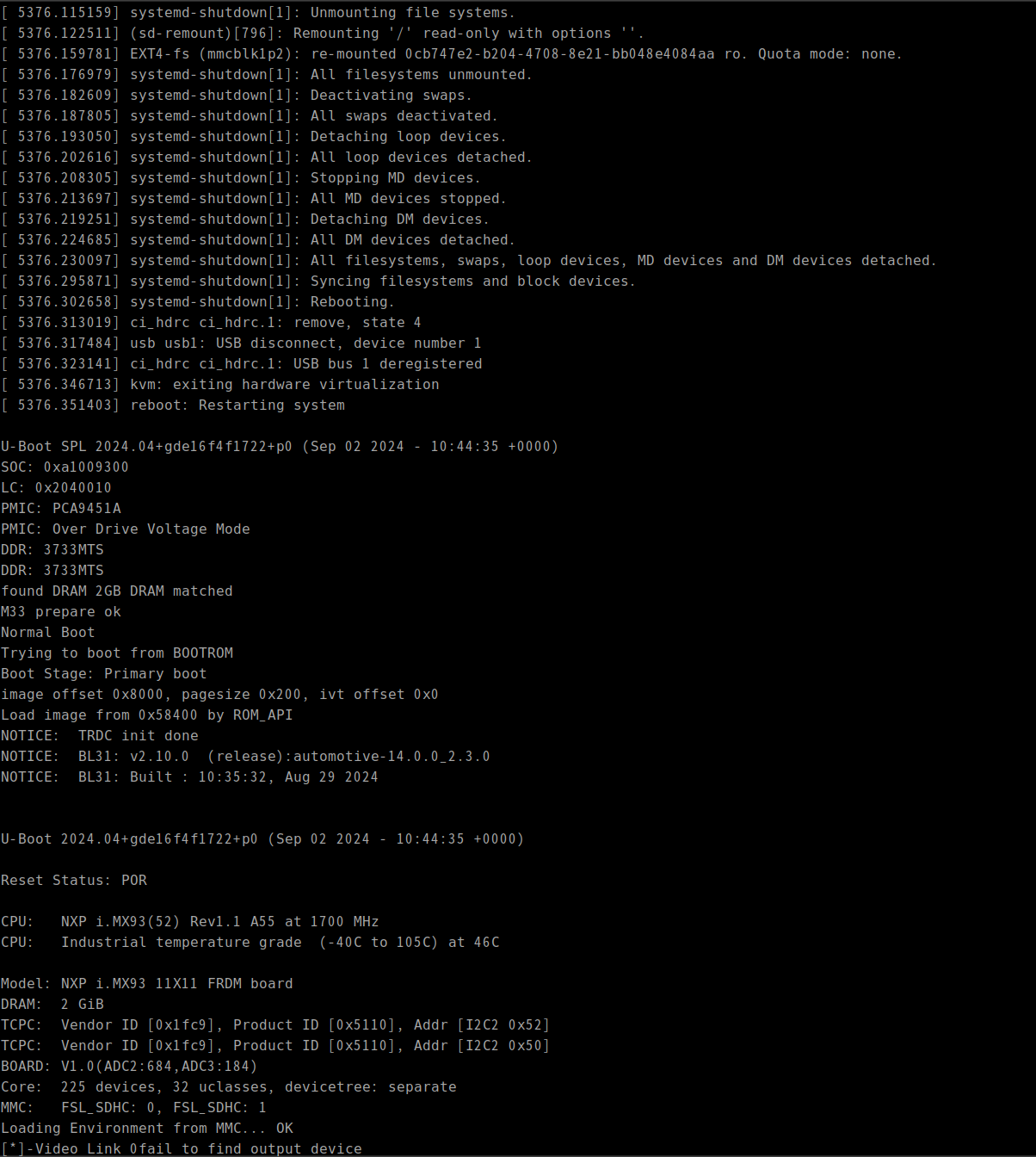
Press the Enter key in the terminal to stop the boot sequence.
Enter the following to switch the modified DTB file. This will change the output GPIO port of the PWM peripheral.
$ setenv fdtfile=imx93-11x11-frdm-pwm.dtb
$ saveenv
Restart with the following command:
$ bootd3-7. Connecting the servo motor
Following these steps, you should now be able to output a PWM signal from GPIO_IO05.
First, connect the servo motor to the FRDM i.MX 93 development board.
Three signals are required to control a servo motor.
| Pin | CABLES color | Commentary |
|---|---|---|
| PWM | Orange | PWM signal |
| VCC | Red | POWER SUPPLIES |
| GND | Brown | Ground |
Servo motors can experience significant power consumption fluctuations depending on the external load, which can affect the stability of POWER SUPPLIES.
Therefore, ideally, the servo motor should be powered from a separate POWER SUPPLIES, but since we are only using it to power a small webcam, we will power it from the FRDM i.MX 93 development board.
Please refer to the following link for the pinout of CONNECTORS on the FRDM i.MX 93 development board.
UM12181: FRDM-IMX93 Board User Manual
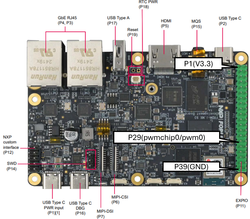
GPIO05, VCC, and GND are output from the EXPI CONNECTORS on P11.
| Pin Number | Name |
|---|---|
| 2,4 | +5V |
| 6, 9, 14, 20, 25, 30, 34, 39 | GND |
| 29 | GPIO05 (PWM) |
In this article, we connected P2 (+5V), P39 (GND), and P29 (PWM) as shown in the diagram below.
3-8. Control of Servo Motors
Now that the servo motor is connected, let's try controlling it.
The output of the PWM signal is controlled through files located under /sys/class/pwm.
First, enable the PWM peripheral.
# 3-4で設定したPWMペリフェラルの有効化
$ cd /sys/class/pwm/pwmchip4
$ ls
device	export	npwm  power  subsystem	uevent	unexport

# pwmを有効にする
$ echo 0 > export

# pwm0が見えるようになる
$ ls
device	export	npwm  power  pwm0 subsystem	uevent	unexport
Next, we'll configure the pwm0 parameters. Let's first look at the enabled pwm0 file.
$ cd pwm0
$ ls
capture  duty_cycle  enable  period  polarity  power  uevent
The following is a summary of each file.
| File name | Commentary |
|---|---|
| capture | This is used when using input mode. We won't be using it this time. |
| duty cycle | Specify the ON time for PWM in nanoseconds. |
| enable | Controls whether the PWM output is enabled or disabled (0: disabled, 1: enabled). |
| period | Specify the duration of one PWM cycle in nanoseconds. |
| polarity | This switches the polarity of the PWM output. We won't be using it this time. |
| power | For POWER SUPPLIES management. We won't be using it this time. |
| uevent | The kernel uses this. We won't be using it this time. |
In short, to output a PWM signal, you just need to write to duty_cycle, period, and enable.
As shown in Figure 3-1, the servo motor to be controlled has a period of 50 ms and a control pulse width of 0.5-2.4 ms.
Therefore, writing to the file as follows will cause the servo to rotate.
# 1サイクルを50ms(= 50000000ns)に設定
$ echo 50000000 > period
# パルス幅を0.5ms(= 500000ns)に設定
$ echo 500000 > duty_cycle
# PWMを出力開始
$ echo 1 > enable
From now on, the motor will rotate if you write a value to duty_cycle within the range of 500000 (0.5ms) to 2500000 (2.5ms).
If you are controlling it from a program, open the file described above and write to it.
4. Implementation of face detection
4-1. Introduction to the eIQ Model
NXP has released an AI demo that runs on i.MX 93.
This includes demos of object detection, hand gesture detection, face recognition, and image classification.
For more details, please refer to NXP's i.MX Machine Learning User's Guide 9.eIQ demos.
4-2. Running the Face Detection Model
Various demos are stored in the /usr/bin/eiq-examples-git directory.
Since the model is not prepared in the initial state, we will run a python script to download and convert the model from the web.
$ cd /usr/bin/eiq-examples-git
$ python3 download_models.py
This Python script downloads the model used in the demonstration and performs a Vela transformation for processing on the i.MX 93's NPU (Ethos-U).
After the initial setup, you can run the face detection demo using the following command.
$ cd face_recognition
$ python3 main.py -i /dev/video0 -d /usr/lib/libethosu_delegate.so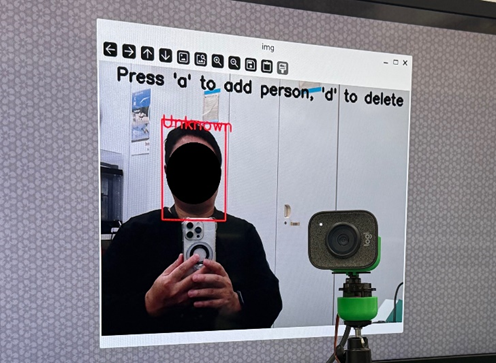
In the face detection demo, bounding boxes are displayed around the faces of people in the screen, and you can register the names of those people using KEY BOARD.
For more details, please refer to section 9.eIQ demos in the i.MX Machine Learning User's Guide.
5. Building a person tracking camera
5-1. Tracking Algorithm
We will create a demo that tracks faces using a face detection model.
In the demo we ran in the previous chapter, we obtained the coordinates of the face using face_detection.py.
We will apply this mechanism to implement the following process.
1. Obtain the coordinates of the face.
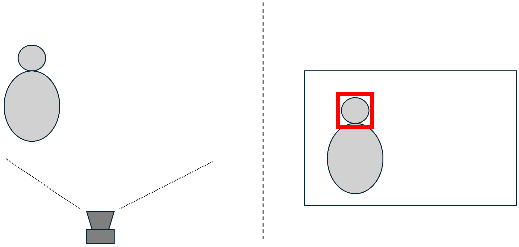
In the face detection demo, the coordinates (x1, y1, x2, y2) of the detected face are obtained in the following section.
        x1, y1, x2, y2 = box.astype(np.int32)
        h, w, _ = img.shape
        x1 = max(x1-PADDING, 0)
        x2 = min(x2+PADDING, w)
        y1 = max(y1-PADDING, 0)
        y2 = min(y2+PADDING, h)
        cv2.rectangle(img, (x1, y1), (x2, y2), (0,0,255), 2)
2. Calculate the center coordinates of the face.
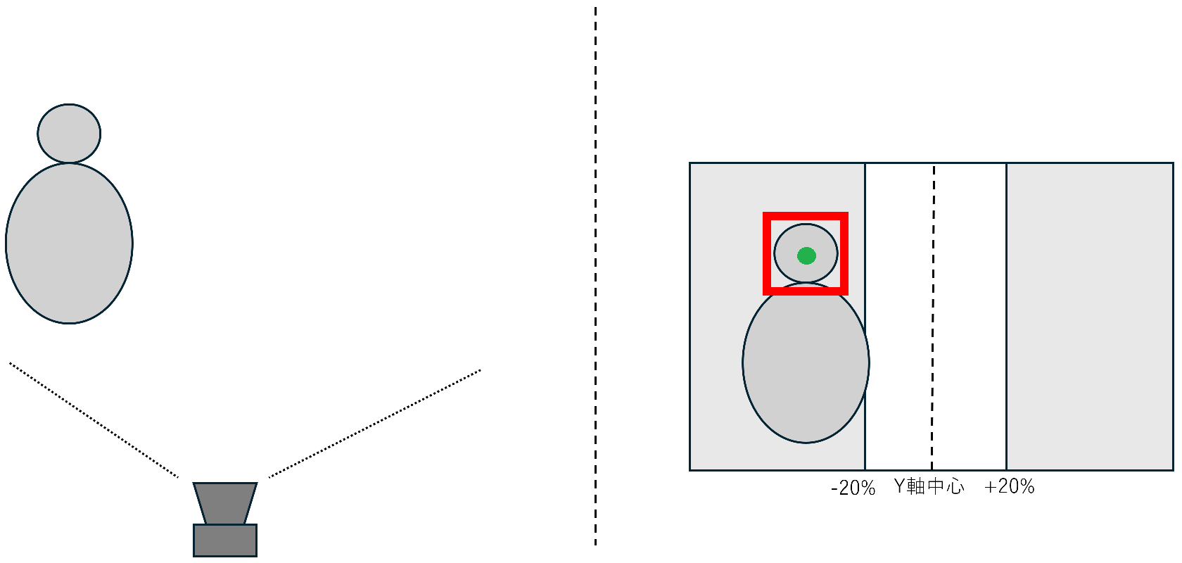
Since we have obtained the face coordinates (x1, y1, x2, y2), we calculate the center coordinates of the face using the following code.
        cx = (x1 + x2) // 2
        cy = (y1 + y2) // 2
3. If the X value of the face's center coordinates is not within ±20% of the screen center, the camera will move towards the center.
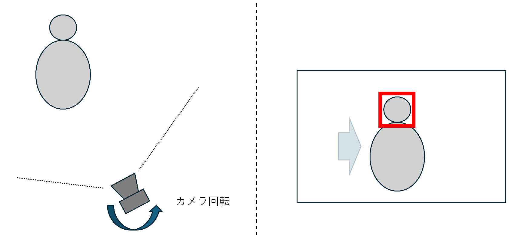
The following process moves the servo and shifts the camera towards the center when the X coordinate is more than 20% away from the center.
The reason we've disabled the camera's reaction within ±20% of the center is to prevent it from becoming overly sensitive and jerky as it tries to return to the center.
        center_left = int(w * 0.4)   # 中央20%の左端
        center_right = int(w * 0.6)  # 中央20%の右端
        if cx < center_left:
            # 画面の左側に顔がある → サーボを「左」に少し動かす
        elif cx > center_right:
            # 画面の右側に顔がある → サーボを「右」に少し動かす
        else:
            # 中央20%以内なら何もしない
5-2. Operational Demo
Let's actually run the demo we created.
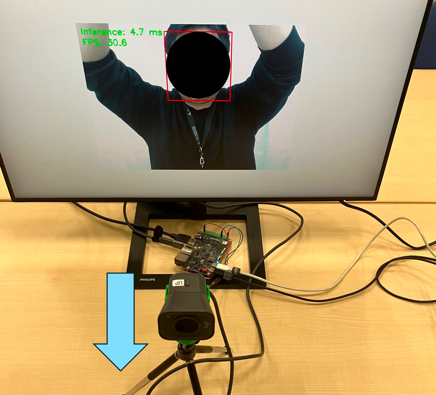
The camera is facing forward and recognizing the person's face.
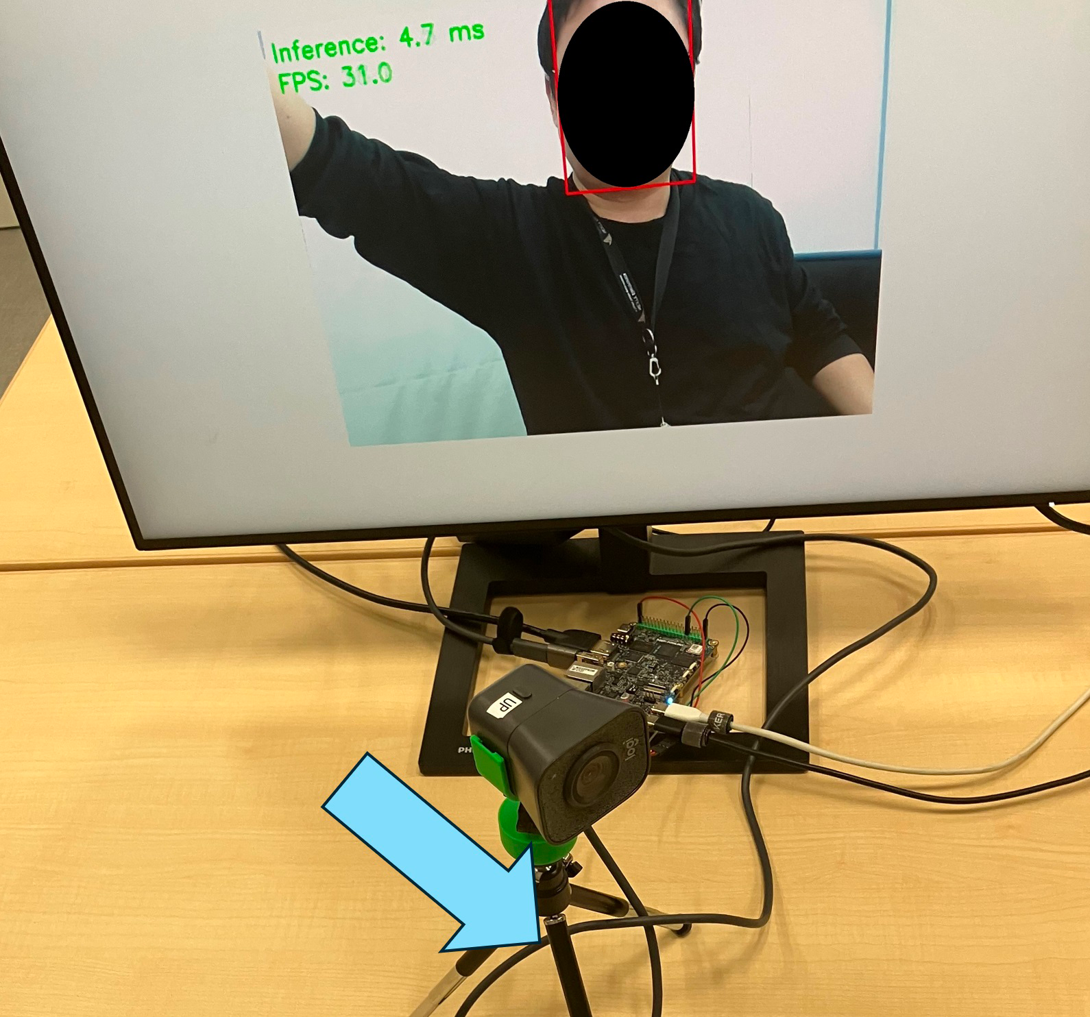
The character has moved from the front to the right side of the camera.
The camera tracks the subject and rotates to keep the person in the center of the frame.
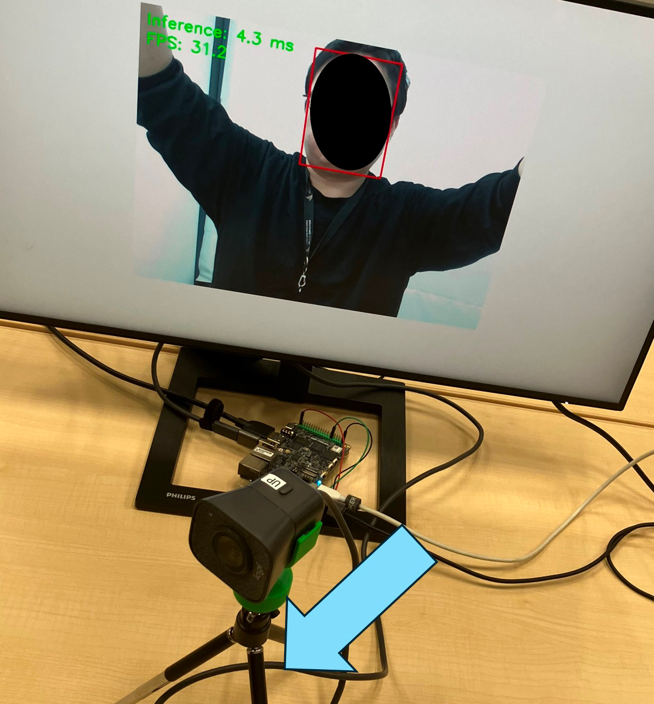
Similarly, the camera has been moved to the left.
As expected, the camera tracks the subject and rotates to keep the person in the center.
Summary
Thus, the i.MX 93 offers excellent edge AI capabilities and numerous peripherals for controlling the device, making it easy to build edge AI applications.
In addition to the face detection model used in this demonstration, the i.MX 93 demo also offers various other demos, including gesture detection, image classification, and object recognition, allowing you to immediately experience the capabilities of edge AI.
Furthermore, edge AI offers advantages such as real-time capabilities, protection of private information, and low power consumption.
By leveraging these characteristics, a variety of products and solutions could be envisioned, including applications such as those listed below.
- Mobile carts, robots (person detection, sensor/IO control)
- Smart doors (person detection, gesture detection, sensor/IO control, integration with Matter)
- Factory automation (human detection, image classification, sensor/IO control)
We hope this article will help solve your challenges and enhance the added value of your products.
Furthermore, NEXTY Electronics' Development Department handles product development and technical support using i.MX series products other than the i.MX 93 introduced here.
This column provides an overview. For more detailed information, please inquire individually.
We can also introduce you to a variety of other products that will meet your needs, so please feel free to inquire.