This is a technical blog by the development team at Nexty Electronics.
We will be sharing information about hardware and software development projects utilizing the products we handle.
This time, we'd like to introduce an IoT system that eliminates the need for battery replacement, which aims to continuously power a BLE microcontroller and various sensor devices by utilizing Exeger Operations AB's indoor/outdoor photovoltaic SOLAR BATTERIES "Powerfoyle ™", NGK Corporation's SECONDARY BATTERIES "EnerCera®", and Nisshinbo Micro Devices Inc. 's energy harvesting POWER SUPPLIES supply IC.
Solution Introduction
IoT devices equipped with sensors and communication functions are increasingly being introduced in factories, warehouses, and other facilities. However, battery-powered devices require periodic battery replacement, which increases the labor required for replacement work and can pose safety risks depending on the installation location.
Therefore, we have been working on developing an IoT system that uses energy harvesting technology that can generate power even in indoor environments, eliminating the need for battery replacement.
Overview

Exeger Operations AB's indoor/outdoor SOLAR BATTERIES "Powerfoyle ™" generates electricity, which is then converted to voltage by Nisshinbo Micro Devices Inc. 's energy harvesting POWER SUPPLIES IC. This power is then used to charge NGK Corporation's ultra-thin, compact lithium-ion SECONDARY BATTERIES "EnerCera®," and this power is used to drive microcontrollers and various sensor devices.
Features
-
The Powerfoyle provides constant POWER SUPPLIES to the EnerCera while also charging it, and powers the microcontroller and sensor device. By operating the microcontroller and sensor device intermittently and meeting the condition of "power consumption < charging power" for the EnerCera, it is possible to operate the microcontroller and sensor device semi-permanently without changing the battery.
-
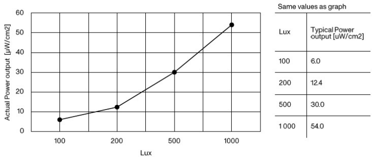
The product we are using this time, Powerfoyle-Indoor, operates under both indoor and outdoor light. The typical power generation per square centimeter is as follows:
Source: https://www.exeger.com/uploads/2023/12/Product-Brief-Powerfoyle-Indoor-v3.0.pdf
-
This system utilizes Leafony *2, a compact, energy-efficient platform for IoT prototyping, making it possible to easily configure a variety of sensor systems without the need for soldering (compatible software development is required separately).
*2: "Leafony" is a registered trademark of LEAFONY SYSTEMS, Inc.
System Configuration
System Block Diagram
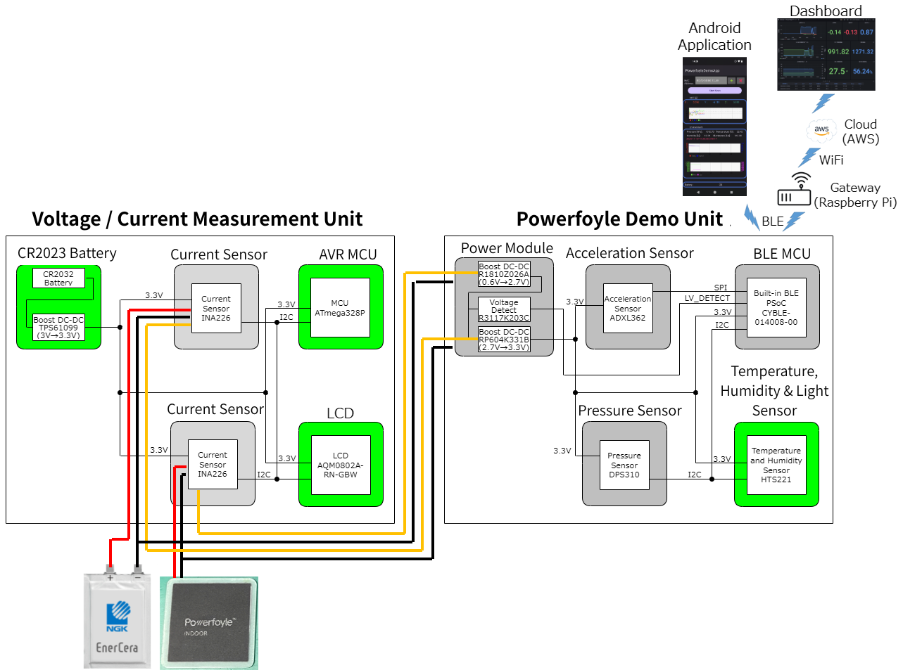
The block diagram of the system developed this time is shown below.
-
Powerfoyle unit
This unit generates electricity using Powerfoyle and charges the EnerCera, which is then used to drive BLE microcontrollers and various sensor devices.
The voltage of approximately 0.6V generated by the Powerfoyle is boosted to 2.7V by Nisshinbo Microdevices' step-up DC/DC converter and charged to the EnerCera (the charging voltage of the EnerCera is 2.7V).
The sensors include an acceleration sensor, ATMOSPHERE SENSORS, a temperature HUMIDITY SENSORS, and ILLUMINANCE SENSORS. The BLE microcontroller acquires acceleration data from the acceleration sensor as the system operates, and broadcasts the acceleration data together with the BLE advertisement signal. The BLE microcontroller acquires data from ATMOSPHERE SENSORS, temperature/ HUMIDITY SENSORS, and ILLUMINANCE SENSORS through intermittent operation once every three minutes, and broadcasts the data from each sensor together with the BLE advertisement signal. -
Voltage/Current Measurement Unit
This unit runs on POWER SUPPLIES (CR2032 button battery) independent of the Powerfoyle unit to accurately visualize the amount of power generated by the Powerfoyle and the charge/discharge rate of the EnerCera. Separate ELECTRIC CURRENT SENSORS are provided for the Powerfoyle and EnerCera, and the acquired voltage/current is displayed on the LCD. -
Android Application
The sensor data can be viewed on the app on the Android device that receives the sensor data acquired by the Powerfoyle unit and transmitted from the BLE microcontroller. -
Dashboard
As with the Android application, the sensor data sent from the BLE microcontroller is received by the Gateway, which then transfers the data to the cloud (AWS), where it can be viewed on the Dashboard.
System appearance photo
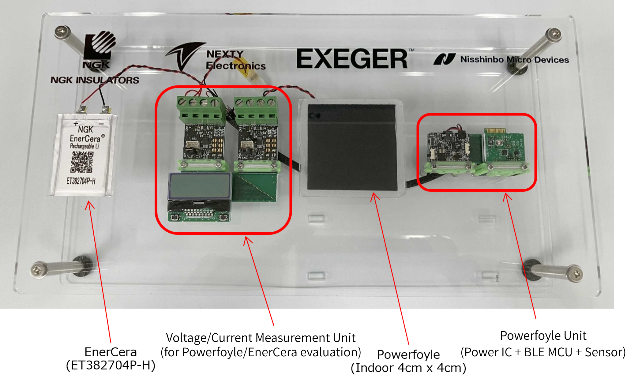
Introducing key items
-
Indoor/outdoor photovoltaic SOLAR BATTERIES “Powerfoyle TM”
・Manufacturer: Exeger Operations AB
・Model number: Powerfoyle-Indoor
Features: Cell size approximately 16cm 2, standard power output 480uW (at 500lux)
Description: This next-generation SOLAR BATTERIES uses dyes to absorb light and generate electrons using that energy, making it capable of generating electricity even under indoor light. It is a lightweight, flexible, and durable renewable energy solution with a high degree of design freedom.
-
Ultra-thin and compact lithium-ion SECONDARY BATTERIES "EnerCera®"
・Manufacturer: NGK Corp.
・Model number: ET382704P-H
Features: Nominal capacity 20mAh, 2.7V constant voltage charging, discharge current 40mA (typical), 300mA (peak)
Description: This ultra-compact, thin SECONDARY BATTERIES combines the advantages of a capacitor and a lithium-ion SECONDARY BATTERIES. Its ultra-thin design allows it to be bent, has low self-discharge, and can charge weak power sources such as SOLAR BATTERIES without leaking. It also boasts excellent safety.
-
Low current step-up DC-DC CONVERTERS for energy harvesting
Manufacturer: Nisshinbo Micro Devices Inc.
・Model number: R1810Z026A
・Features: Low current consumption (IQ: 600nA), startup at 9µW (low illumination)
Description: This device converts minute amounts of power generated by SOLAR BATTERIES into practical voltages. It is equipped with a control function that achieves low current consumption and maximizes power generation efficiency.
System operation introduction
We will now explain how the battery replacement-free IoT system introduced here works.
-
Sensor data transmission in Powerfoyle units
Data obtained from the acceleration sensor, ATMOSPHERE SENSORS, temperature HUMIDITY SENSORS, and ILLUMINANCE SENSORS installed in the Powerfoyle unit is sent to the Android device or Gateway via the BLE advertisement signal.
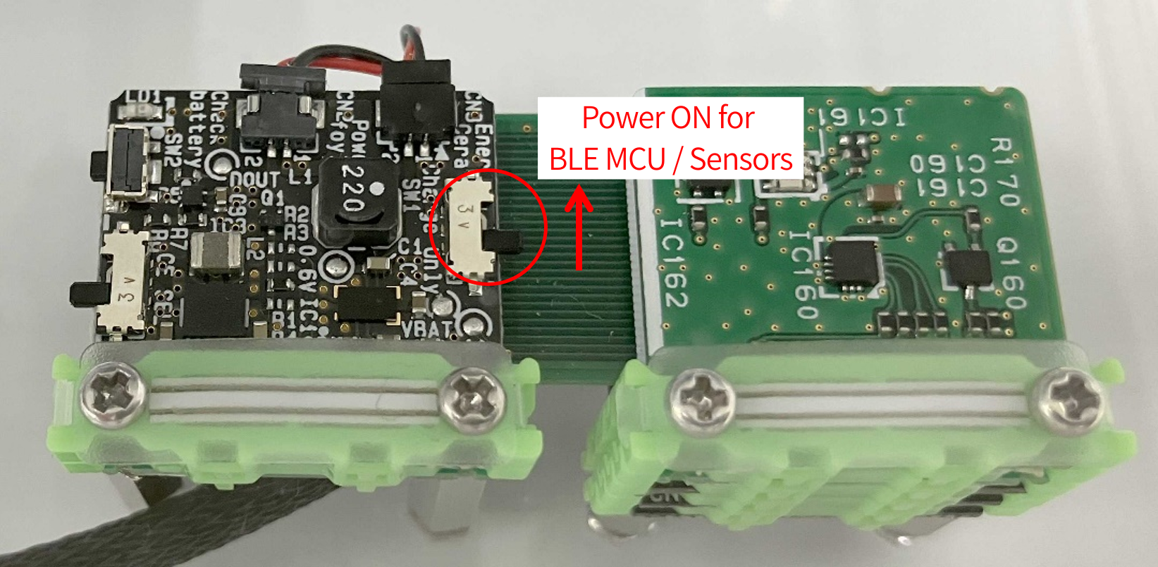
Turn on POWER SUPPLIES SWITCHES of the Powerfoyle unit. Power is supplied to the BLE microcontroller and each sensor device, and sensor data can be viewed on the Android app or on Dashboard via the Gateway. ATMOSPHERE SENSORS, temperature HUMIDITY SENSORS, and ILLUMINANCE SENSORS operate intermittently every 3 minutes, while the acceleration sensor operates in real time when it detects 0.5G.
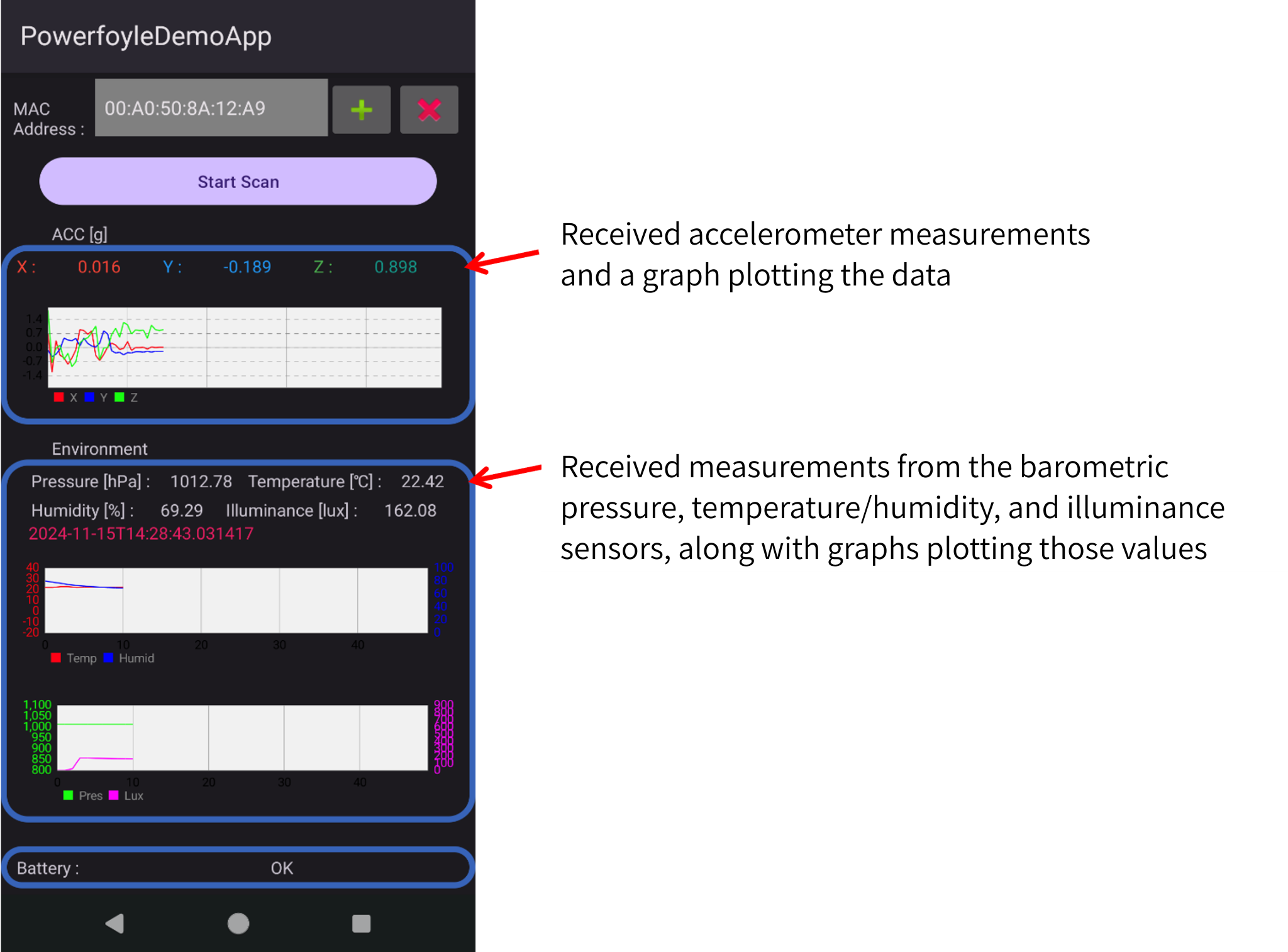
The acquired sensor data is displayed on the Android app as shown below.
The acquired sensor data is displayed on the Dashboard as shown below.
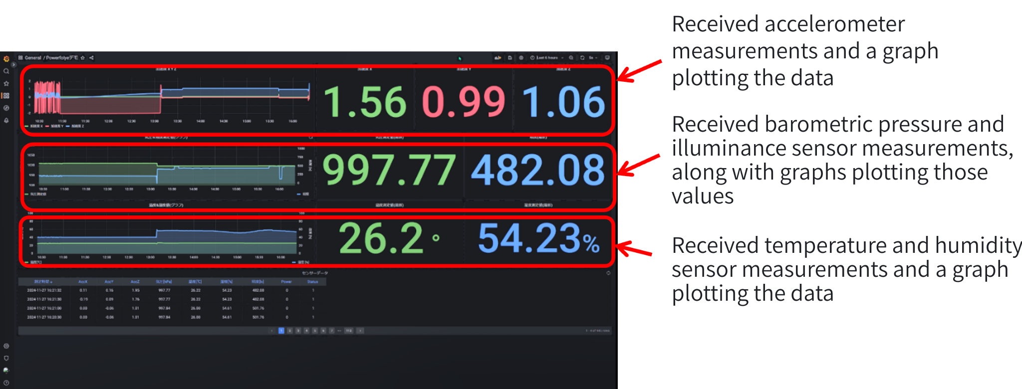
-
Voltage/current measurement of Powerfoyle/EnerCera with voltage/current measurement unit
ELECTRIC CURRENT SENSORS built into the voltage/current measurement unit measures the amount of power generated by the Powerfoyle and the amount of charge and discharge by the EnerCera, and displays the measurement results on the LCD on the unit.
Turn on POWER SUPPLIES SWITCHES of the voltage/current measurement unit.
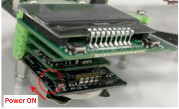
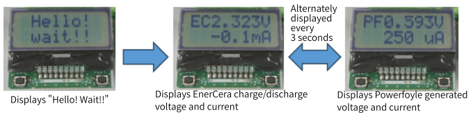
After the LCD displays "Hello! Wait!!", the EnerCera charging/discharging voltage/current and the Powerfoyle generating voltage/current will be displayed alternately at 3-second intervals.
Conditions under which battery replacement is not required
In this system, we verified the power consumption and charging power conditions required to eliminate the need for battery replacement by combining SOLAR BATTERIES "Powerfoyle" and SECONDARY BATTERIES "EnerCera." We verified these conditions through desk calculations and operation confirmation using an actual device, and confirmed the feasibility of the system.
-
Desk verification
To avoid the need for battery replacement, EnerCera must operate in a way that satisfies the condition of "power consumption < charging power."
1) Calculating power consumption per hour
The power consumption per hour was calculated based on the operating time per hour of the BLE microcontroller and various sensors used in the Powerfoyle unit and the current consumption (some of which was actually measured) listed on the datasheet. The 85% efficiency of the DC/DC converter that generates the 3.3V POWER SUPPLIES for the BLE microcontroller and various sensors was also taken into account.
Current consumption per hour
| Current consumption per hour when the acceleration sensor is active | 0.0000003 mAh |
| Current consumption per hour when ATMOSPHERE SENSORS is active | 0.00002025 mAh |
| Current consumption per hour when the temperature/humidity/ ILLUMINANCE SENSORS is active | 0.00001792 mAh |
| Current consumption per hour when the BLE microcontroller is active (during BLE communication) | 0.0461 mAh |
| Current consumption per hour when idle | 0.0000525 mAh |
| Current consumption per hour during sleep | 0.6892 mAh |
| Total current consumption per hour | 0.7354 mAh |
Power consumption per hour
| POWER SUPPLIES voltage of the load (BLE microcontroller, various sensors) | 3.3 V |
| Total current consumption per hour | 0.7354 mAh |
| Power consumption per hour | 2.427 mWh |
| Power consumption per hour (Taking into account the 85% efficiency of the DC/DC converter that generates the 3.3V) | 2.855 mWh |
⇒ Power consumption per hour: 2.855mWh
② Consideration of the illumination required for power generation
Based on the information in the graph below, we have considered the illuminance at which Powerfoyle can generate charging power that exceeds the power consumption per hour listed in ①.
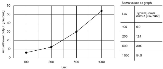
Source: https://www.exeger.com/uploads/2023/12/Product-Brief-Powerfoyle-Indoor-v3.0.pdf
When illuminated with 100 Lux of illumination, approximately 6 uW can be generated per 1 cm2, but since the size of the Powerfoyle used here is approximately 16 cm2, it can generate 16 times as much, or approximately 96 uW. As a result of calculations, an illumination of 4300 Lux is required to obtain charging power that exceeds the power consumption per hour (2.855 mWh). (Details below)
⇒Since 96uW can be generated at 100 Lux, a simple calculation shows that the power generation amount is 4.128mW at 4300 Lux. Taking into account the 70% efficiency of the DC/DC converter that boosts the 0.6V generated by the Powerfoyle to 2.7V, it is estimated that a charging power of 2.889mW can be obtained at 4300 Lux.
-
Actual machine operation check
We tested the actual operation of the Powerfoyle unit *3 to see if it met the condition of "power consumption < charging power" for EnerCera at an illuminance of 4300 Lux.
*3: Data is collected from ATMOSPHERE SENSORS, temperature HUMIDITY SENSORS, and ILLUMINANCE SENSORS every 3 minutes, and transmitted via BLE advertisement signals.
① Preparation of operation confirmation environment
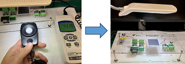
As shown in the photo below, we installed an LED light on top of the Powerfoyle unit and adjusted it to a height where the Powerfoyle would emit approximately 4300 Lux, while measuring the illuminance with a light meter.
I turned on POWER SUPPLIES SWITCHES of the Powerfoyle unit and checked the voltage of the EnerCera before and after starting the operation check on the LCD of the voltage/current measurement unit. The results are as follows.
EnerCera voltage before operation check: 2.578V
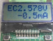
EnerCera voltage immediately after starting operation check: 2.575V
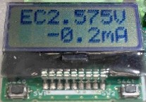
EnerCera voltage after 20 minutes of operation check: 2.578V
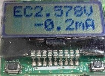
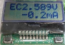
EnerCera voltage after 2 hours of operation: 2.589V
EnerCera voltage after 4 hours of operation: 2.604V
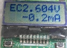
From the results of ② above, it was confirmed that although the voltage of the EnerCera dropped temporarily due to temporary power consumption caused by turning on POWER SUPPLIES immediately after the operation check began, it was subsequently charged little by little. This confirmed that the charging power exceeded the power consumption under the conditions of the desktop verification results (illumination 4300 Lux) even while the Powerfoyle unit was operating.
Summary
This time, we introduced an IoT system developed by Nexty Electronics that does not require battery replacement. This system solves POWER SUPPLIES supply issues for various sensor devices installed in factories, warehouses, etc., and provides sustainable energy solutions, thereby improving business efficiency and achieving sustainable operations.
If you found this article interesting or would like more information, please feel free Inquiry. We look forward to hearing your questions and comments.
NEXTY Electronics Initiatives
NEXTY Electronics Corporation is a core company in the Toyota Tsusho Group's electronics business and boasts one of the largest scales in the field of car electronics. Leveraging its core technologies and products, it responds to the needs of customers and society in a wide range of fields, provides solutions to social issues, and contributes to the realization of a better society.
Additionally, the development team at Nexty Electronics carries out in-house development using the products we handle, as well as contract development (hardware and software development).We are here to help you, including resolving any issues you may have, so please feel free to contact us.