


- NXP Semiconductors NV
- NEXT Mobility
This book outlines the steps involved in using the FRDM-A-S32K118 evaluation board, which features NXP's S32K118 automotive microcontroller, from setting up the development environment to running sample code. It serves as a startup guide for those considering adopting automotive microcontrollers and wanting to begin evaluation inexpensively and easily.
In the first half, we will explain how to install S32 Design Studio and Real-Time Drivers (RTD). In the second half, we will show you how to obtain sample code from the Application Code Hub, read the temperature readings from the PCT2075DP TEMPERATURE SENSORS on the board via I2C, and display them on a PC via UART.
*FRDM: This is the name of an evaluation board provided by NXP, and is pronounced "Freedom".
Overview of this initiative
The complete software package required for developing the FRDM-A-S32K118 (S32 Design Studio, RTD, communication stack, etc.) can be obtained as a bundle from the Automotive Software Package Manager.
- You must have an NXP account.
- Target board: FRDM-A-S32K118
FRDM-A-S32K118 overview
The FRDM-A-S32K118 is an evaluation board equipped with NXP's automotive microcontroller, the S32K118. It features CAN FD, LIN, USB Type-C, JTAG, RGB LEDs, a user push button, a RESET button, and an Arduino header-compatible CONNECTORS.
Because it has an onboard debugger (OpenSDA), you can program and debug using a USB Type-C CABLES and a PC. It also has a JTAG CONNECTORS, so you can connect an external debugger for debugging.
It also features an I2C-connected TEMPERATURE SENSORS, the PCT2075DP, which is used in the sample code in this book. Furthermore, it has an Arduino header-compatible CONNECTORS, allowing you to connect and evaluate various expansion boards.
*The PCT2075DP is not an automotive-certified product (AEC-Q100). The P3T1755DP/Q900 is an automotive-compatible alternative. While TERMINALS-compatible, the P3T1755DP/Q900 is a 3.3V product and has some differences in register configuration and characteristics.
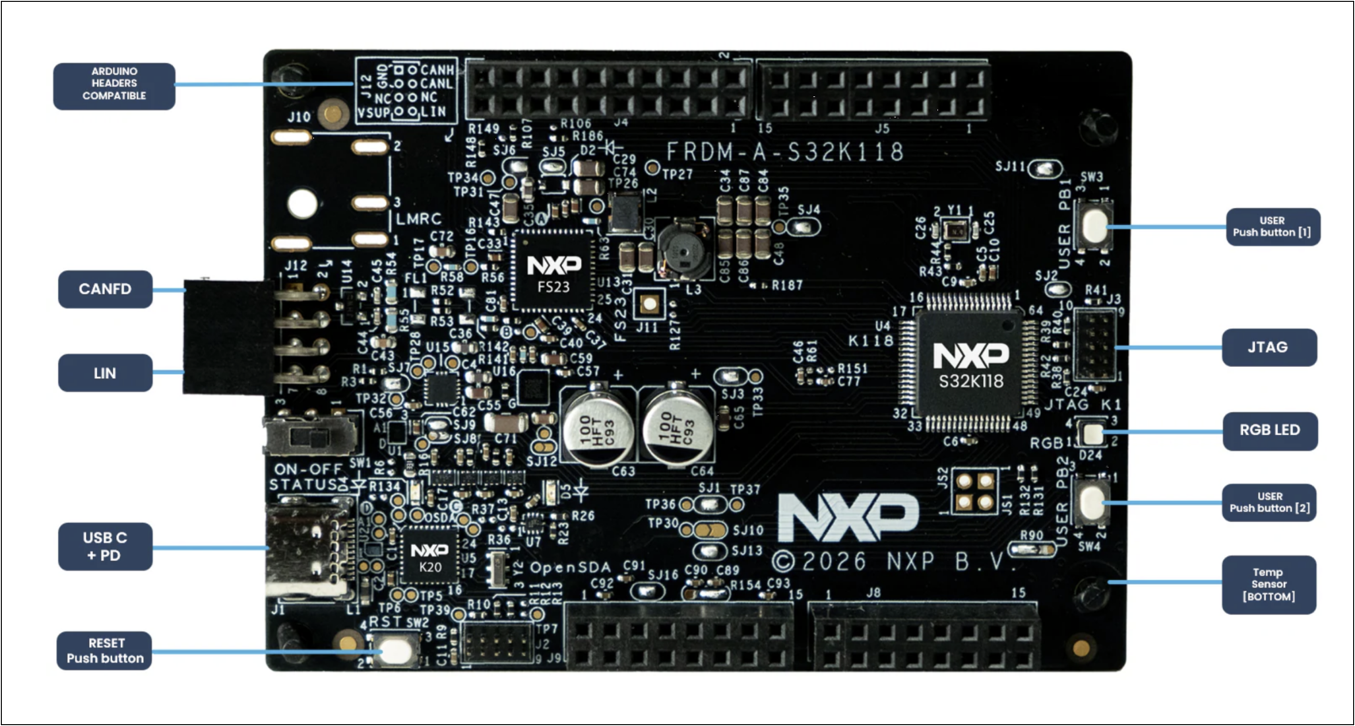
Figure 1 FRDM-A-S32K118 evaluation board
NXP Getting Started Guide and Sign In
Open the Start Guide page
Open the "Getting Started with the FRDM-A-S32K118 Development Board for General-Purpose Automotive Applications" page on the NXP website. Follow the steps, such as "1. Package Contents," and then go to the Automotive Software Package Manager via the FRDM Automotive Bundle link on the "2.1 Software Installation" page (a sign-in screen will appear if you are not signed in).
Automotive Software Package Manager is a web tool for generating software bundles to install.
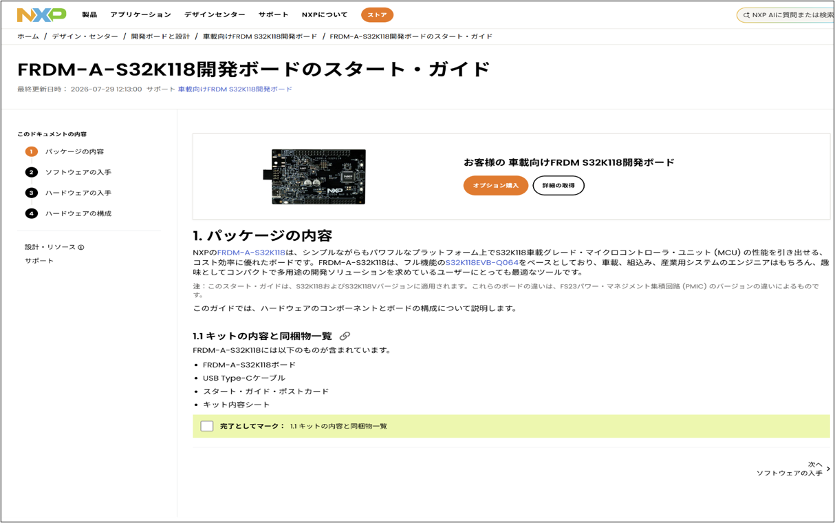
Figure 2 FRDM-A-S32K118 Start Guide Page
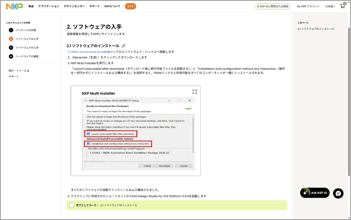
Figure 3: Software acquisition screen
Enter your email address
On the "Sign in to your NXP account" screen, enter your registered email address and click "CONTINUE".
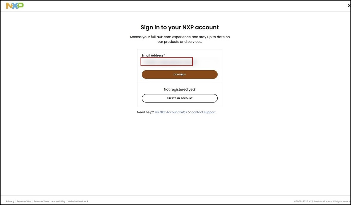
Figure 4: Sign-in screen (enter email address)
Enter your password
Enter your password and click "SIGN IN". Check the "Keep me signed in" option if necessary (uncheck it on shared PCs).
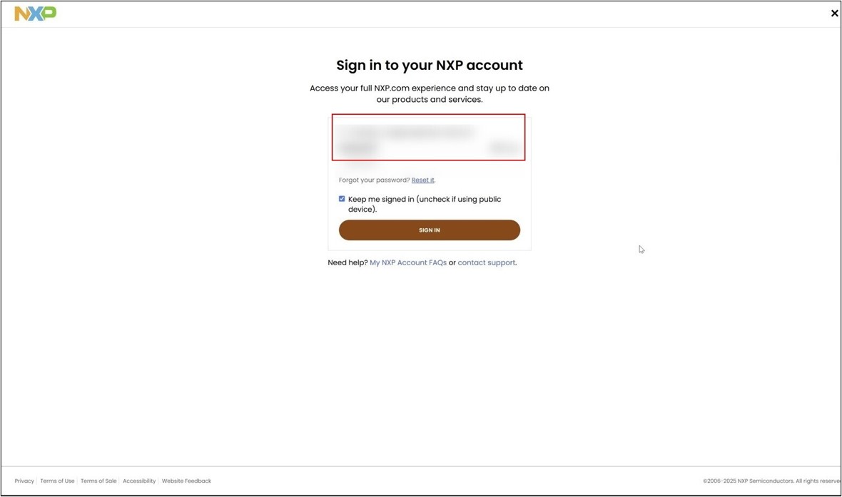
Figure 5 Password entry screen
Enter the one-time password code.
Enter the one-time password code displayed in your smartphone's authentication app (Authenticator) into the "Verification Code" field and click "VERIFY".
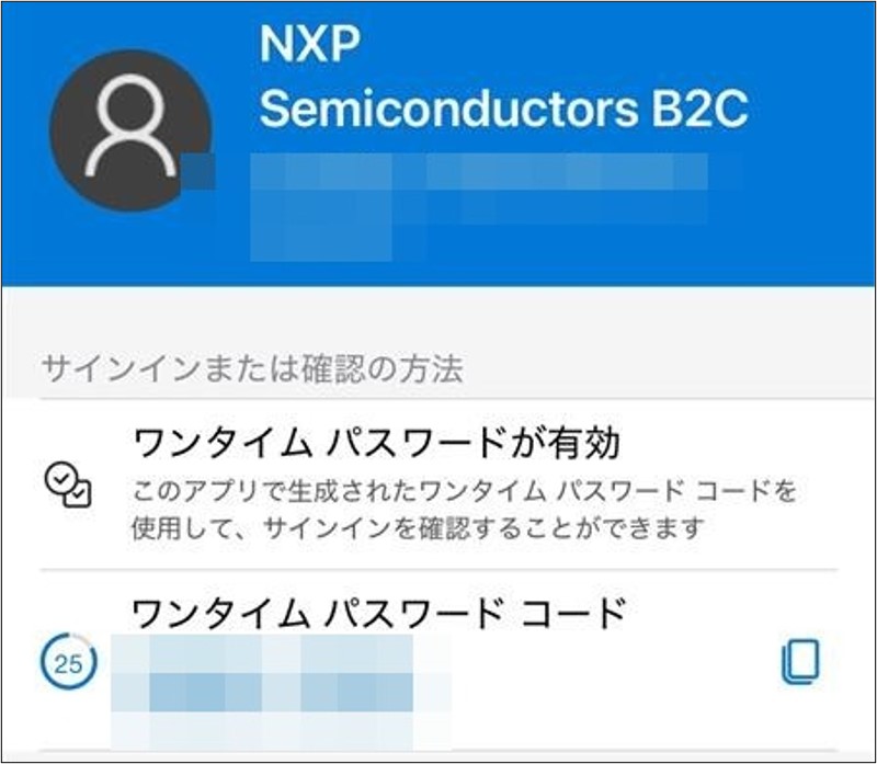
Figure 6 One-time password displayed in the authentication app
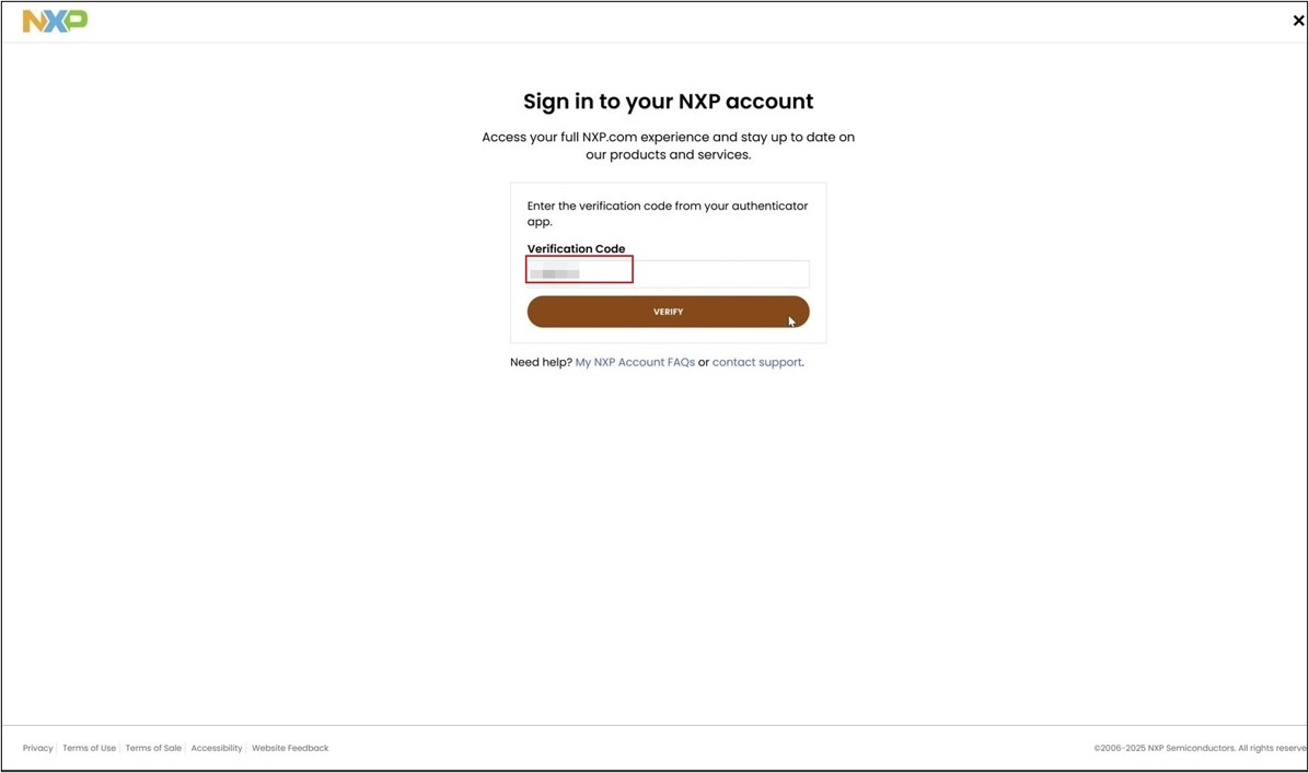
Figure 7 Entering the One-Time Password Code
*If an error message is displayed, please enter the one-time password again.
*The one-time password code is updated every 30 seconds. Please enter the latest code.
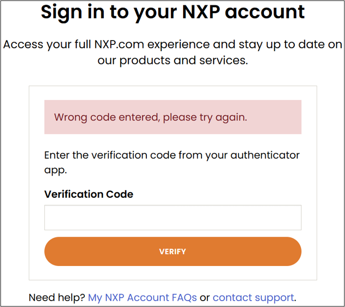
Figure 8 When an error occurs
Having trouble signing in?
Please refer to the "My NXP Account FAQ" for helpful information on how to create an NXP account, troubleshooting if you can't sign in, multi-factor authentication, and more.
Bundle generation (Automotive Software Package Manager)
After signing in, the Automotive Software Package Manager will open.
*If you see the message "Please wait while your session is being created," please wait until the session creation is complete.
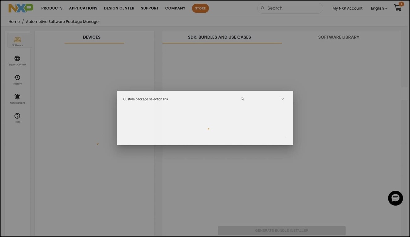
Figure 9: Display during session creation
Select a device and bundle
On the left side, under DEVICES, check the box for General-Purpose MCUs > S32K1.
On the right side, under SDK, BUNDLES AND USE CASES, check the box for "FRDM Automotive Board Installation Package," and then click "GENERATE BUNDLE INSTALLER" at the bottom of the screen.
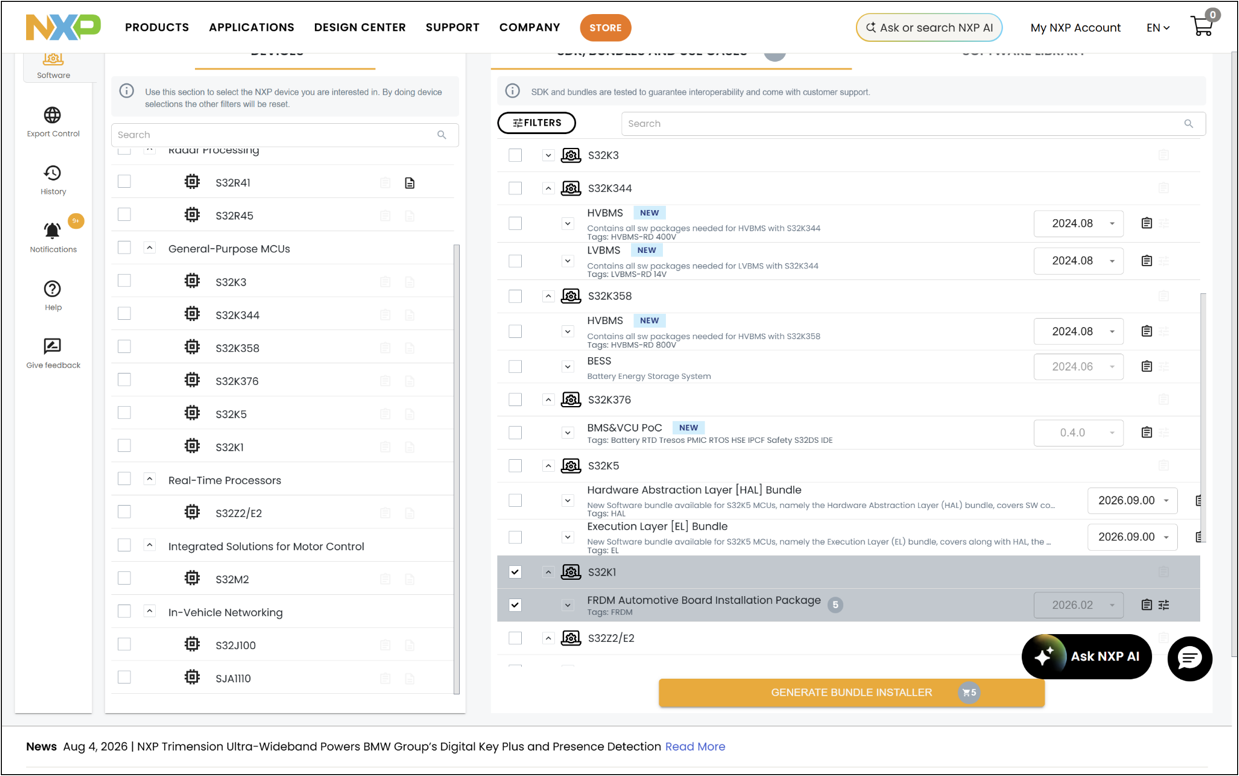
Figure 10: Selection between S32K1 and FRDM Automotive Board Installation Package
Check the package contents.
In "Review package selection," review and select the packages to add to the bundle. In this example, we select Real-Time Drivers 3.0.0 QLP04 and S32 Design Studio and Configuration Tools 3.6.5 and click "NEXT" (LIN Stack, FreeRTOS, TCP/IP Stack, etc. are also available as selections).
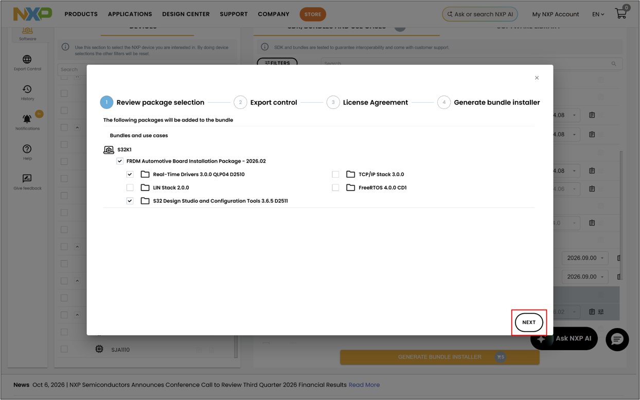
Figure 11: Review package selection
Enter export control information.
In the Export Control Export Compliance Project Inquiry form, enter the product/project type (e.g., Automotive) and application (e.g., development and evaluation of in-vehicle ECUs), and then click "SUBMIT EXPORT CONTROL".
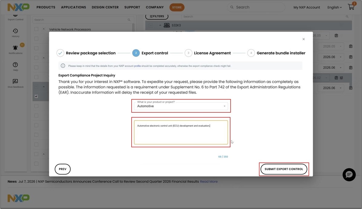
Figure 12 Export Compliance Project Inquiry Input
Confirmation of passing export control checks
The message "The following packages have passed export control checks." will appear, and once the selected packages (Real-Time Drivers 3.0.0 QLP04, S32 Design Studio and Configuration Tools 3.6.5) are listed, click "NEXT".
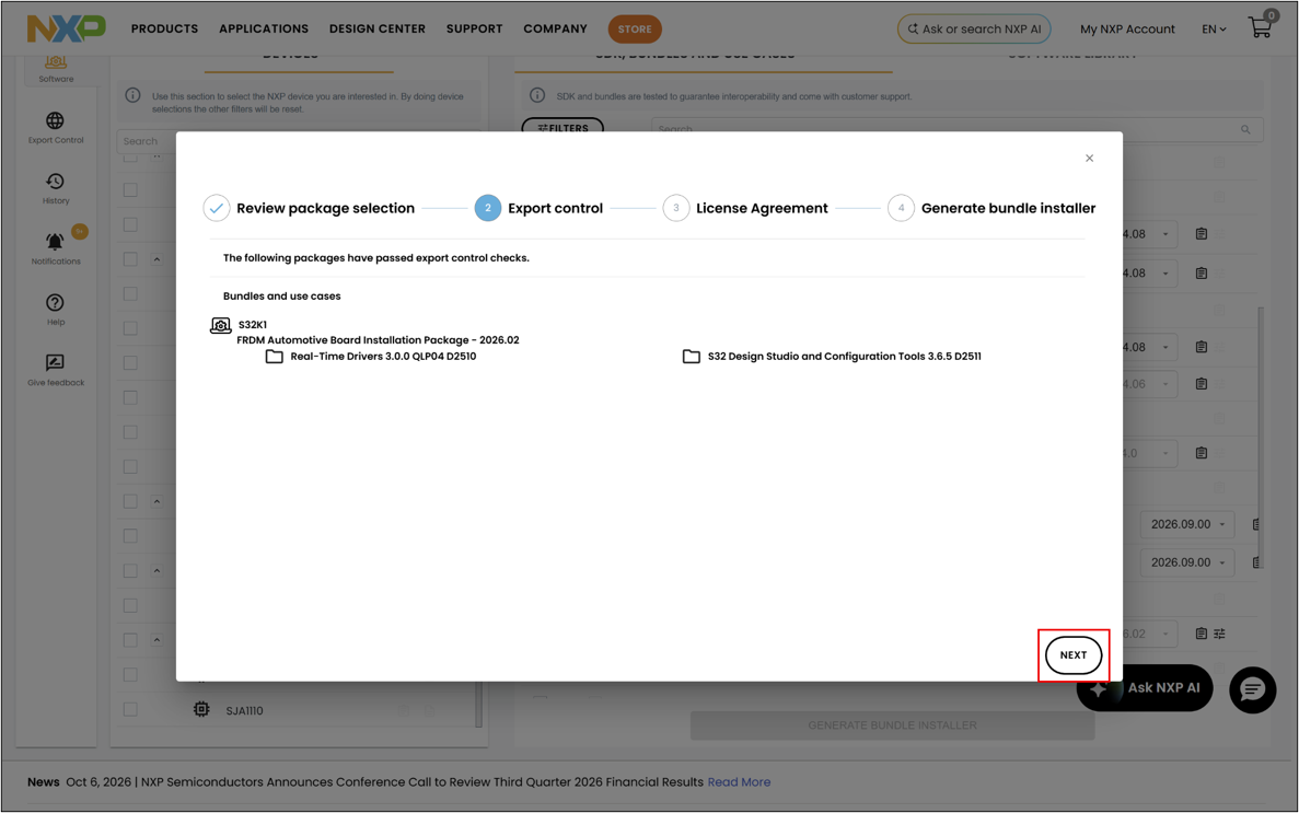
Figure 13 Confirmation of passing export control checks.
I agree to the license.
Read the entire "License Agreement" and click "I ACCEPT THE TERMS OF THE LICENSE AGREEMENT" at the bottom of the page (you cannot click this until you scroll to the bottom).
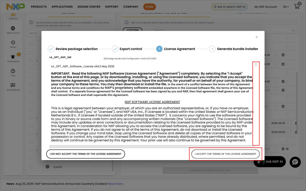
Figure 14 Agreeing to the Bundle Generation License Agreement
Click "DONE" in "Generate bundle installer".
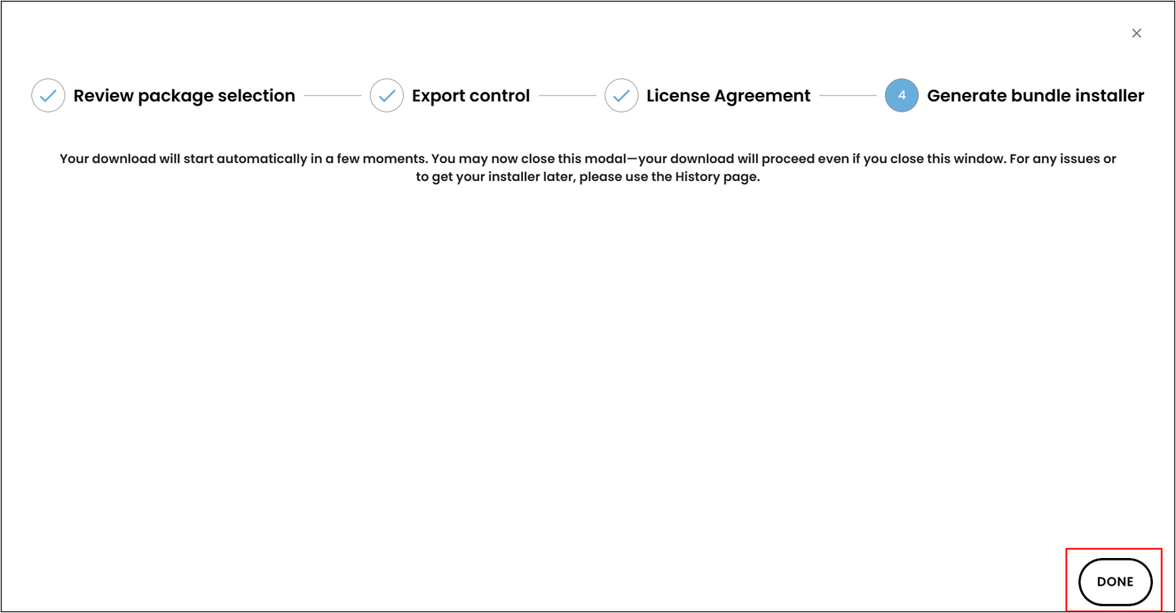
Figure 15 Generate bundle installer screen
Wait for the bundle to be generated.
A message will appear in the lower left corner of the screen saying, "Your bundle is being created. This may take a few moments. You'll be notified when it's ready." The download will start automatically when it's ready.
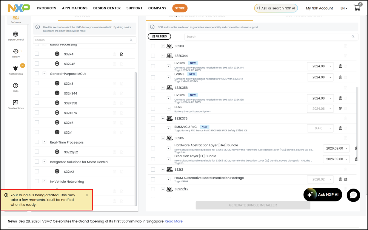
Figure 16 Display during bundle generation
Check the downloaded files.
After a short while, "NXP_Multi_Installer_XX.XX.XX.XXXXXX_setup.exe" and "NXP_Multi_Installer_XX.XX.XX.XXXXXX_User_Manual.pdf" will be saved to your "Downloads" folder.
*The XX.XX.XX.XXXXXX part of the file name represents the date and time of download.
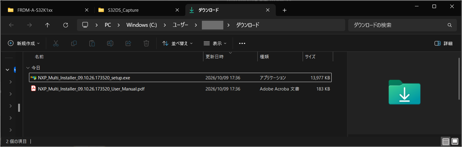
Figure 17 Download folder
*If the download does not start automatically, please click the link in the lower left corner of the screen that says "If your download does not start automatically, please click here to download it manually."
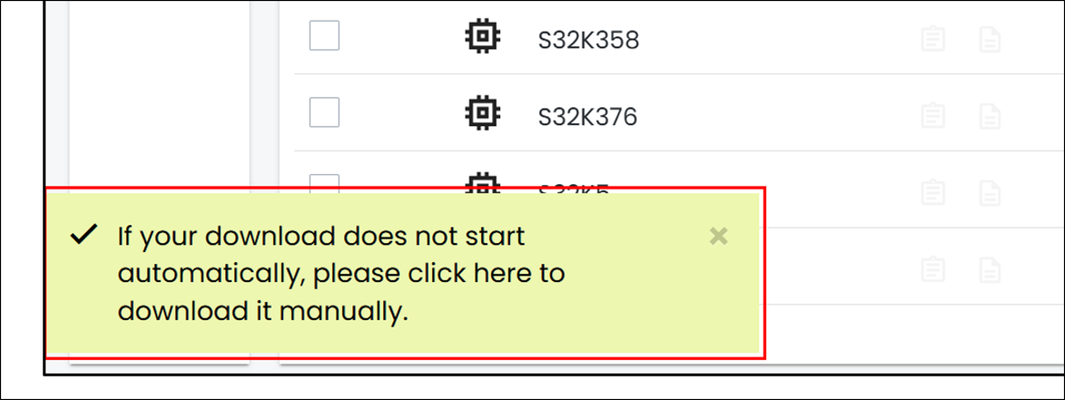
Figure 18: What to do if the download does not start automatically
Download and install using NXP Multi Installer
What is NXP Multi Installer?
NXP Multi Installer is a tool for installing necessary software, such as Real-Time Drivers (RTDs), using software bundles generated by the Automotive Software Package Manager.
Start the setup wizard.
When you run the downloaded NXP_Multi_Installer_XX.XX.XX.XXXXXX_setup.exe, the "Welcome to the NXP Multi Installer Setup Wizard" will appear. Click "Next >".
*As shown in the wizard, the download link within the bundle has an expiration date (approximately 2 hours). If the expiration date has passed, please regenerate the bundle using the Package Manager.
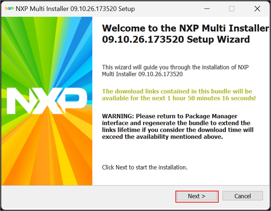
Figure 19 Starting the Setup Wizard (NXP Multi Installer Setup Wizard)
Review the License Agreement (LA_OPT_NXP_Software_License) and click "I Agree".
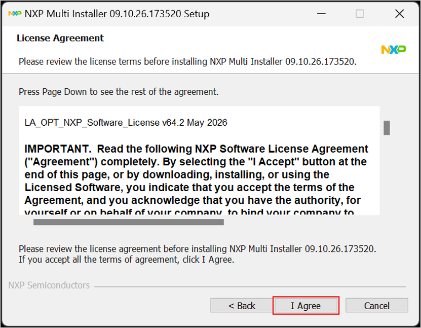
Figure 20: Agreeing to the Installer's License Agreement
On the "Choose Components" screen, select the configuration you want to install. Select "Full" under "Select the type of install," make sure that "Real-Time Drivers" and "S32 Design Studio and Configuration Tools" under S32K1 → Bundles are checked, and then click "Next >".
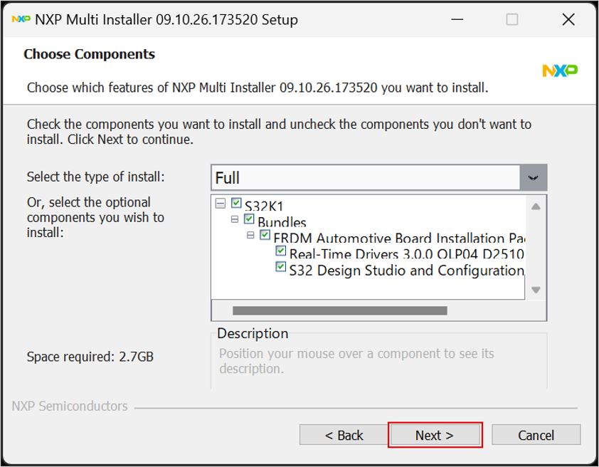
Figure 21 Selecting Installation Configuration (Choose Components)
On the "Choose Download Location" screen, specify the folder where you want to download the package. If the default folder is acceptable, leave it as is. If you want to change it, select the desired location using "Browse..." and then click "Next >".
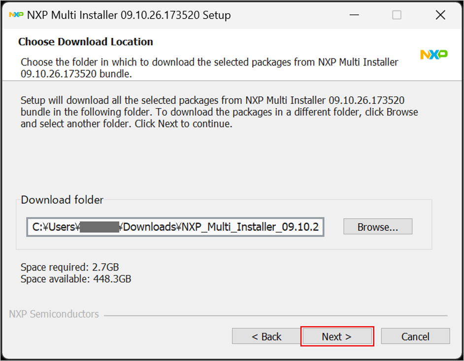
Figure 22 Specifying the download destination folder (Choose Download Location)
On the "Ready to Download the Packages" screen, click "Download". If you want the executable file to launch automatically after downloading, check the box for "Launch executable files after download". We will check this box this time.
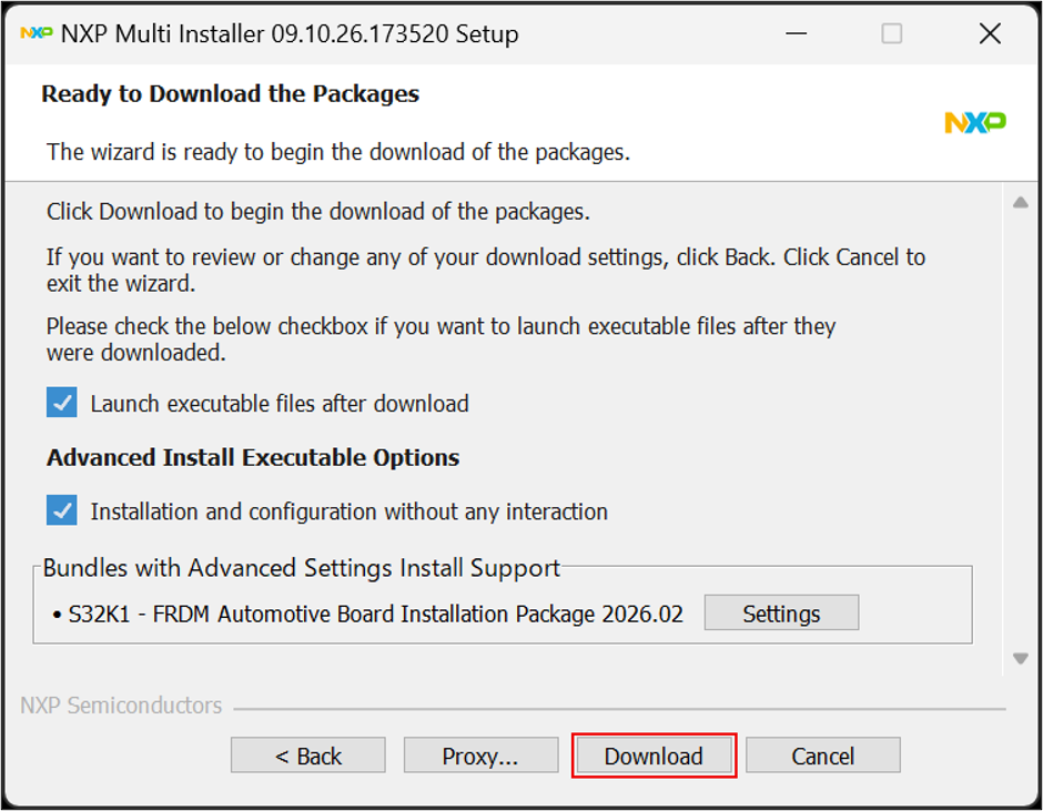
Figure 23 Confirmation of download start (Ready to Download the Packages)
The download and installation of each package (S32 Design Studio 3.6.5 main program, Real-Time Drivers (RTD)) will be performed automatically.
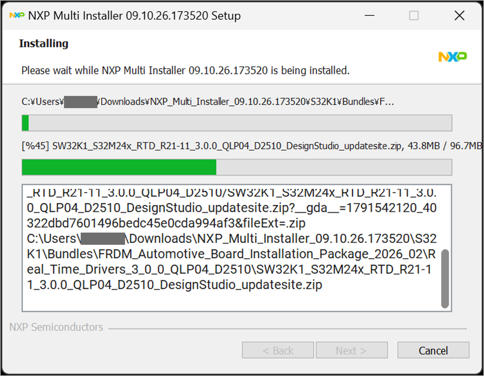
Figure 24 Package download and installation in progress.
In the Advanced Configuration, the S32 Design Studio itself is installed first.
*This process will take some time to complete.
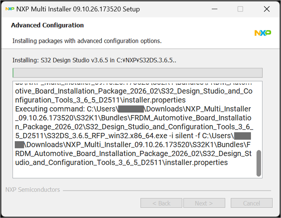
Figure 25: Installation of S32 Design Studio
Next, Real-Time Drivers (RTD) v3.0.0 will be installed.
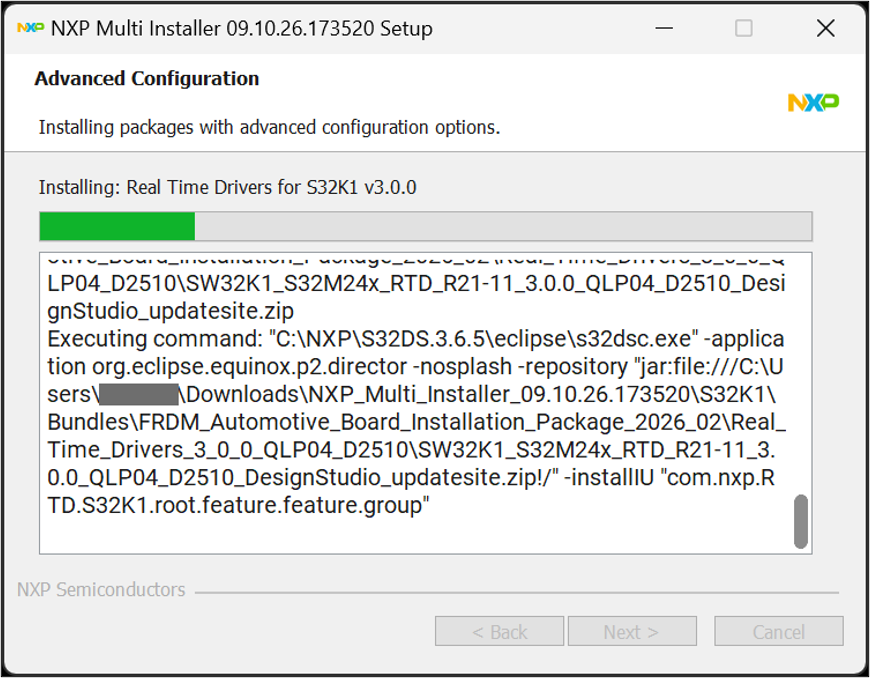
Figure 26 Installation of Real-Time Drivers (RTD)
Once "Completed" is displayed on the "Advanced Configuration" screen, click "Next >".
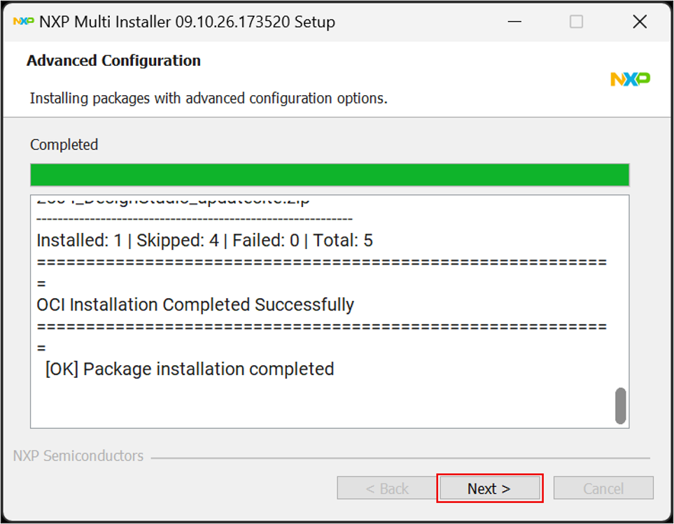
Figure 27 Advanced Configuration (Completed)
After the "Download Complete" screen displays "Download of the packages completed successfully," click "Next >" to exit the wizard.
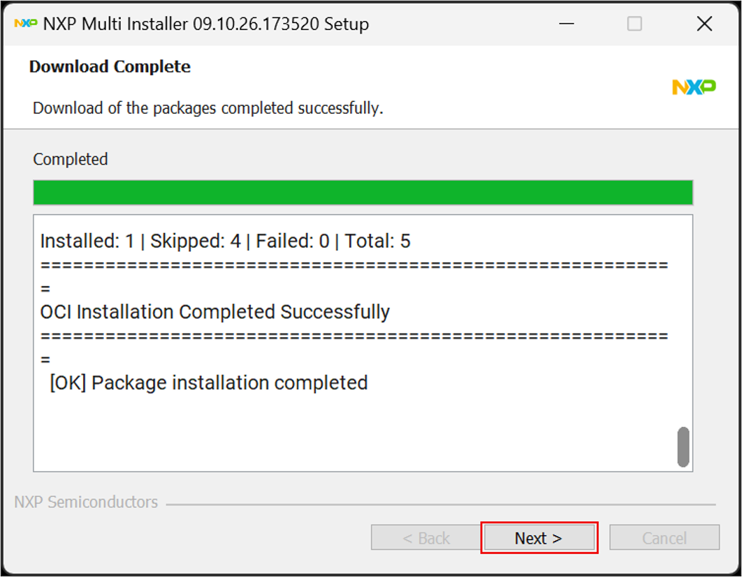
Figure 28 Confirmation of Download Completion
Click "Finish" on the "Completing the NXP Multi Installer Setup Wizard" screen to exit the wizard.
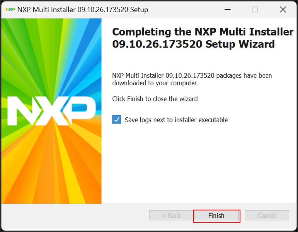
Figure 29 Successful Completion
Precautions
-
*The download link for the bundle will expire after a certain period of time (approximately 2 hours) from the time of generation. If you plan to install after some time has passed, please regenerate the bundle from the Package Manager's History page.
Starting and initial setup of S32 Design Studio
Launch S32 Design Studio
Search for "S32 Design Studio" in the Start menu and launch it.
Specify your workspace (where settings and projects are saved) under "Select a directory as workspace" and click "Launch". If you always want to use the same location, check "Use this as the default and do not ask again".
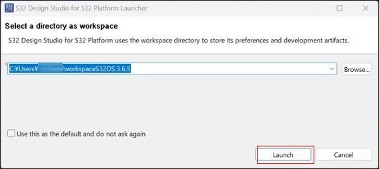
Figure 30 Workspace Selection
Precautions
- Please do not include Japanese characters (full-width characters) in your workspace path.
- Please place your workspace in the shortest possible path (ideally, a path length of less than 200 characters).
- Please use a folder on your local drive, not one stored under cloud storage such as OneDrive or Google Drive.
- Network drives and folders where background syncing is performed may cause build errors or project corruption.
Recommended examples
C:\Users\(username)\workspaceS32DS.3.6.5
S32 Design Studio will launch and the "WELCOME TO S32 DESIGN STUDIO IDE" screen will be displayed.
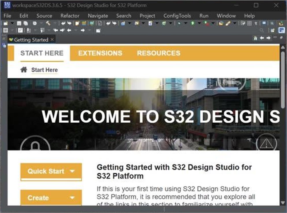
Figure 31: Initial startup of S32 Design Studio IDE
If "S32DS Extensions and Updates" appears, click "Cancel" to close it.
* "S32DS Extensions and Updates" is a feature for installing and updating additional features and software packages (RTDs, plugins, etc.) in S32 Design Studio.
In this procedure, the necessary packages have already been installed using NXP Multi Installer, so you do not need to perform any additional installations from this screen.
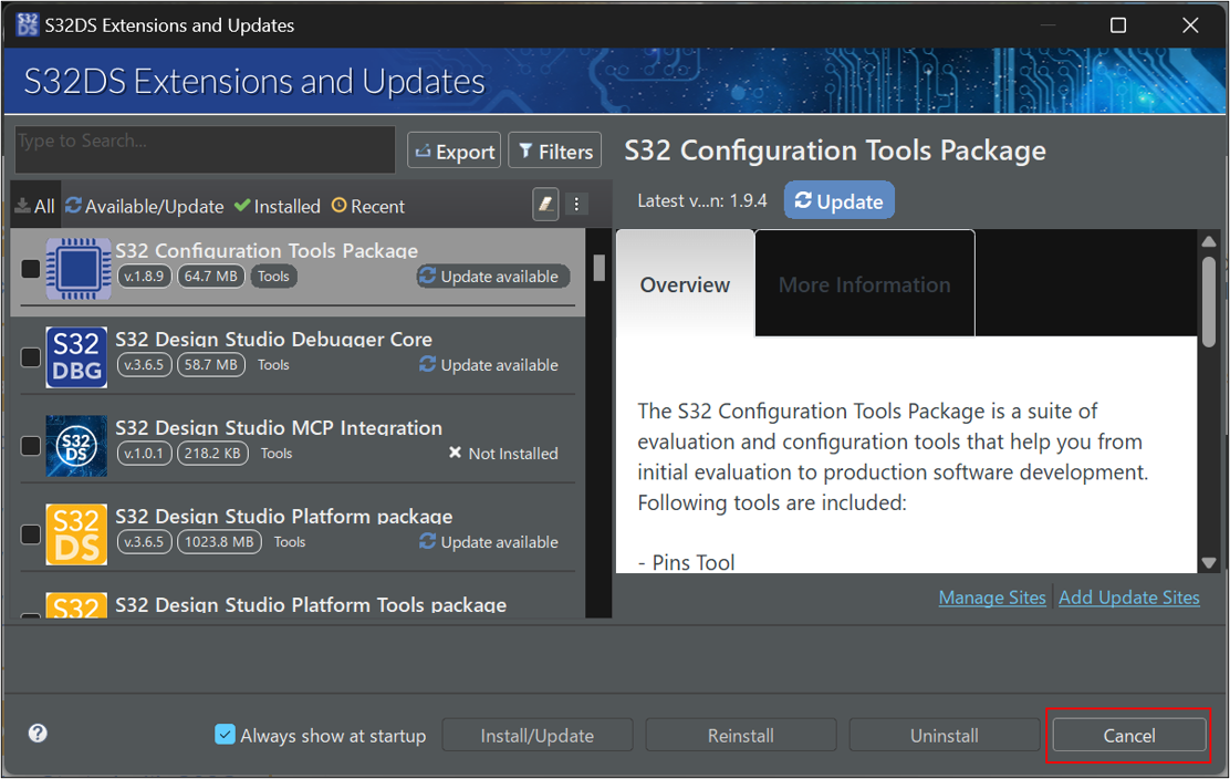
Figure 32 S32DS Extensions and Updates (Close with Cancel)
Click the "x" to the right of "Getting Started".
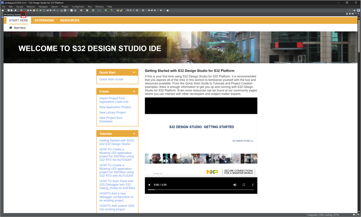
Figure 33 Close the Getting Started tab.
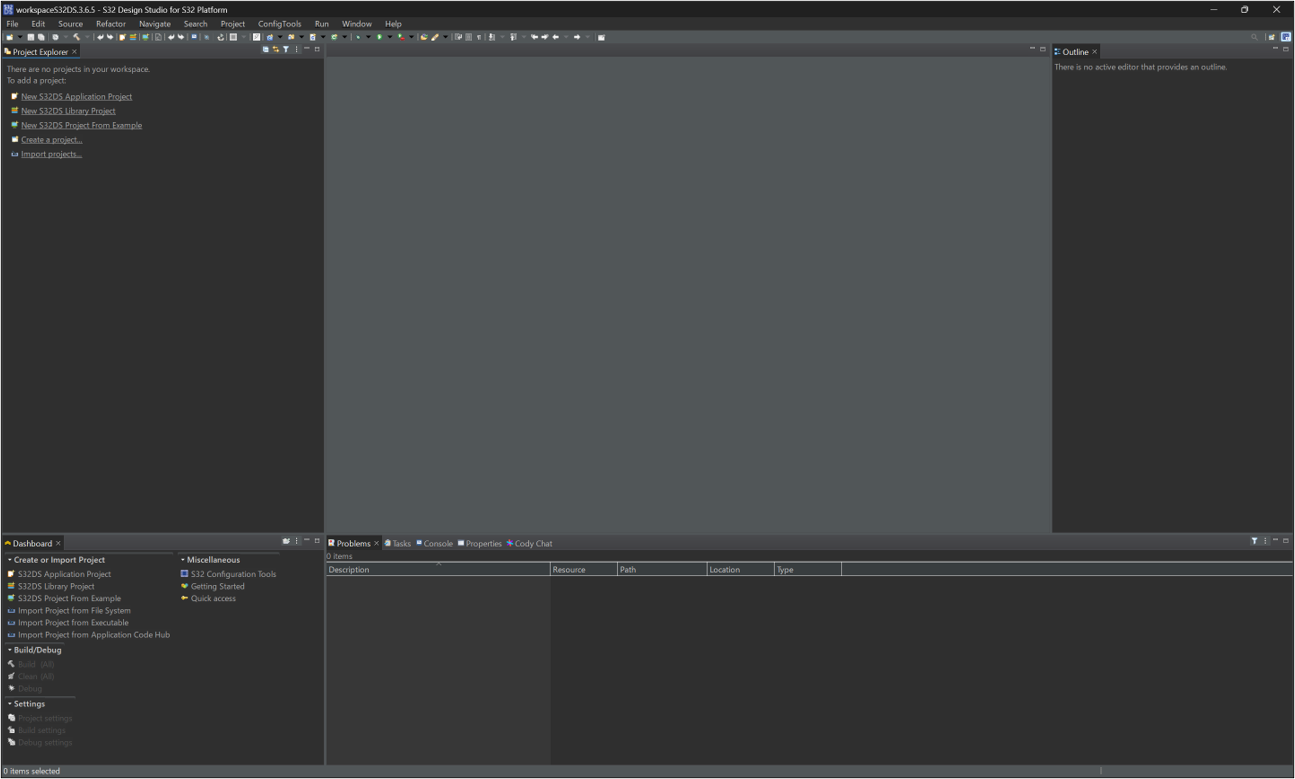
Figure 34: Main screen of S32 Design Studio IDE
Connection method
Now connect the FRDM-A-S32K118 to your computer. Use the included USB-C CABLES or a PD-compatible CABLES. The following steps are excerpts from "4.3.1.2 Startup sequence" in the FRDM-A-S32K118 Hardware User Manual (UM12503).
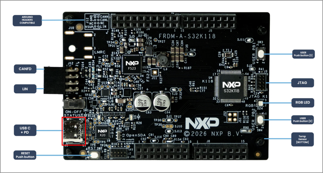
Figure 35 shows the location of the USB-C CONNECTORS (J1).
Power is supplied via the J1 USB-C CONNECTORS on the board. First, SWITCHES SW1 from its initial position to the 2-3 side (On).
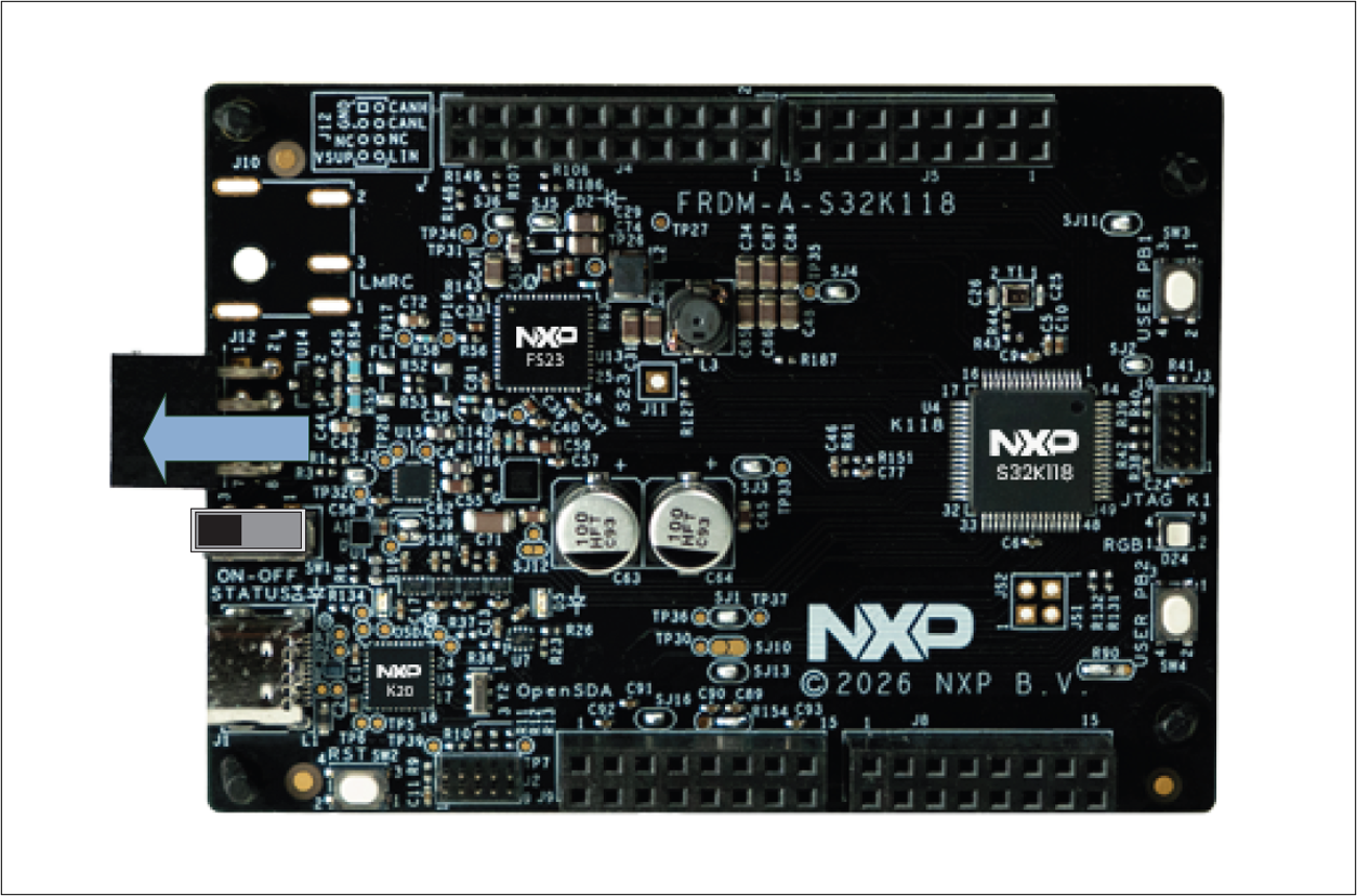
Figure 36 SW1 is set to On.
Once you've turned SW1 on, plug the USB-C CABLES into the J1 CONNECTORS.
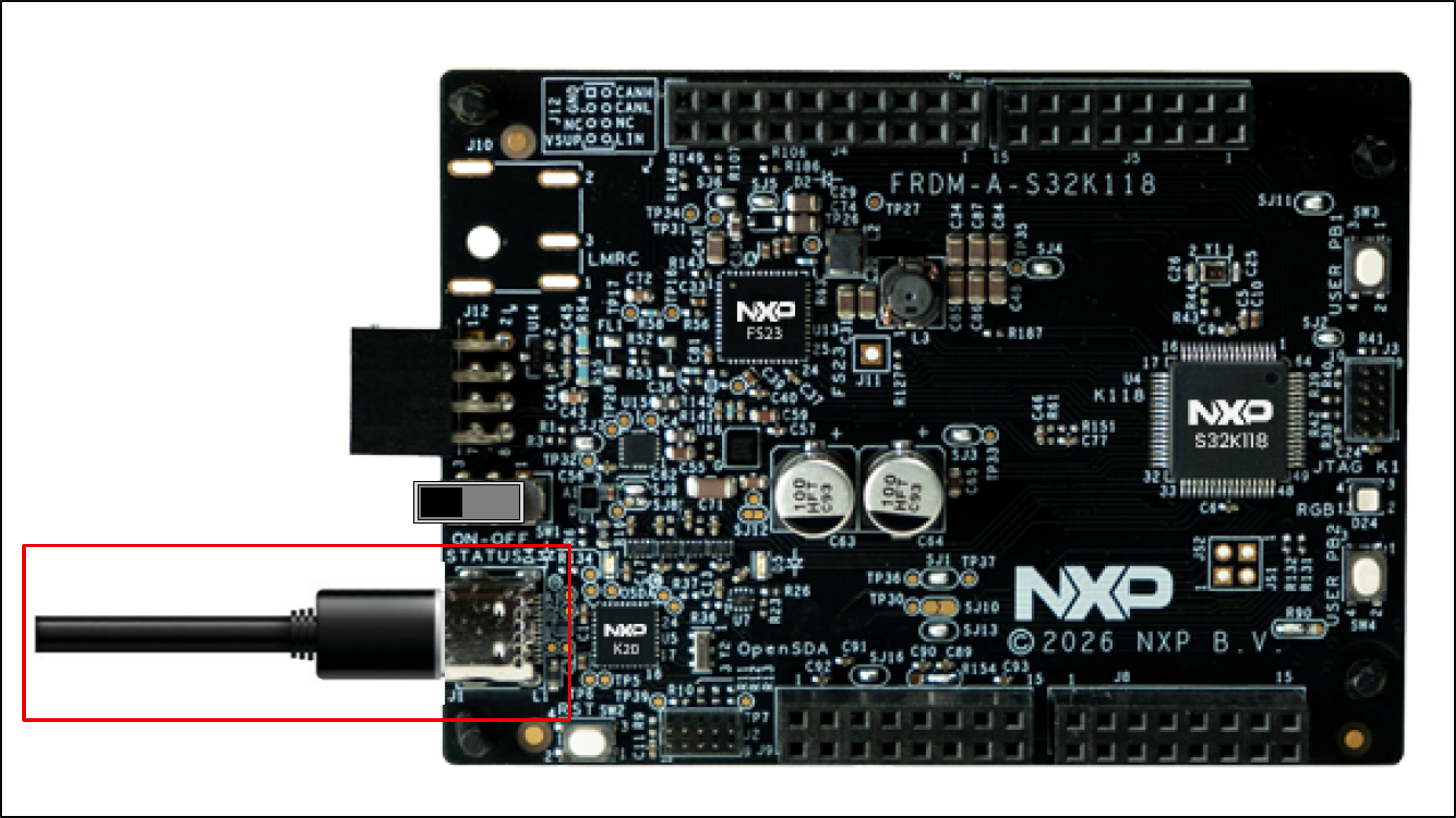
Figure 37 Connecting the USB-C CABLES
When you connect the USB-C CABLES, the OpenSDA status LED (D4) will light up orange, indicating that it is ready to be programmed.
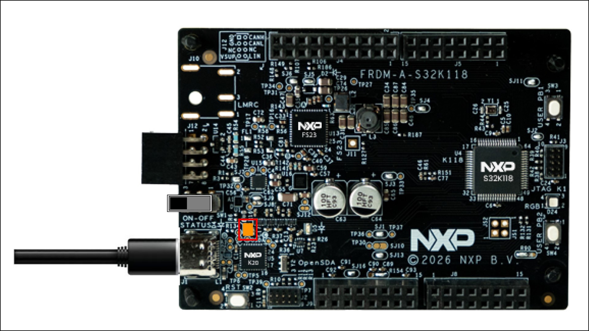
Figure 38 Ready to write
Obtain TEMPERATURE SENSORS sample code from Application Code Hub
Open Application Code Hub from S32 Design Studio.
Application Code Hub (ACH) is a collection of sample code provided by NXP. You can obtain sample projects for microcontrollers and evaluation boards and use them for functional evaluation and application development.
This is the screen you see immediately after launching S32 Design Studio. Import your project from the "Dashboard" panel in the lower left.
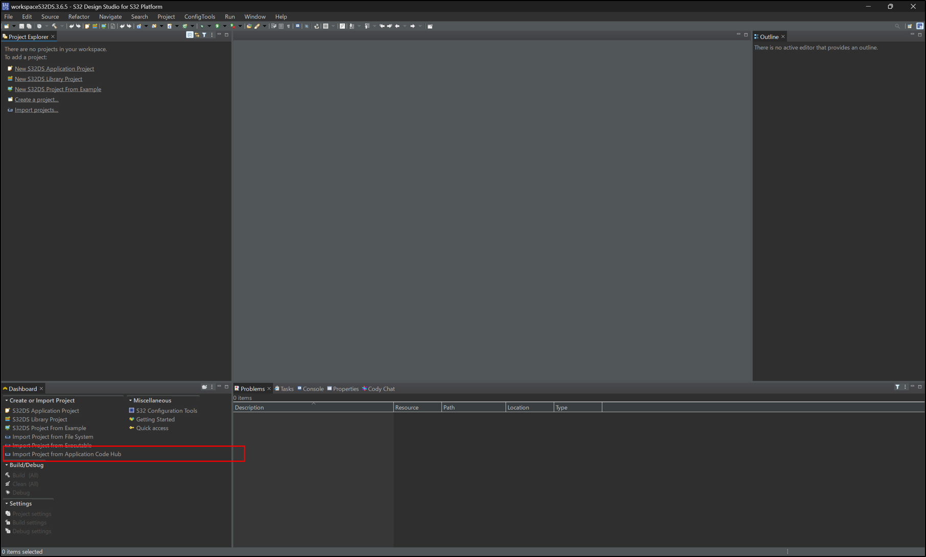
Figure 39 shows the S32 Design Studio screen (the Dashboard is in the lower left).
Figure 40 is a magnified view of the Dashboard in the lower left of the image above. Select "Import Project from Application Code Hub" under "Create or Import Project".
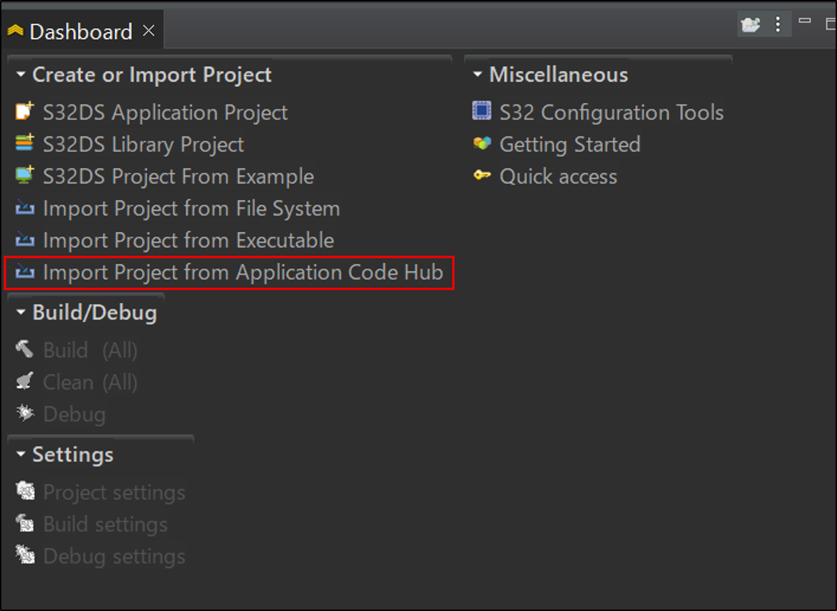
Figure 40 Selecting "Import Project from Application Code Hub" (Dashboard)
Search for sample code for S32K118
Search for "S32K118". From the list, select "Read PCT2075DP Temperature I2C Sensor and Send UART Messages".
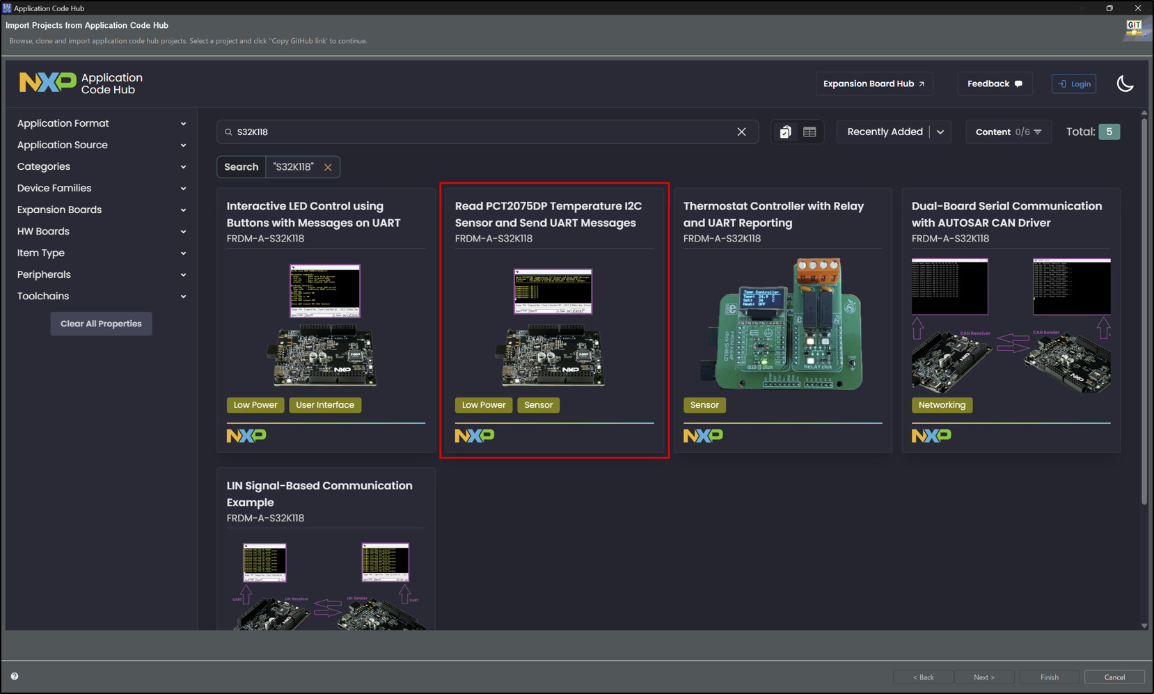
Figure 41: List of projects in Application Code Hub (Search for S32K118)
Check the sample code for TEMPERATURE SENSORS (PCT2075DP).
This sample code reads the temperature reading from the PCT2075DP TEMPERATURE SENSORS via I2C and outputs it to the serial console via UART every second. The instructions for "Read PCT2075DP Temperature I2C Sensor and Send UART Messages" will be displayed. The target board (FRDM-A-S32K118), TEMPERATURE SENSORS (PCT2075DP), and driver used (Lpi2c_Ip / Lpuart_Uart_Ip) are listed, so please check the details.
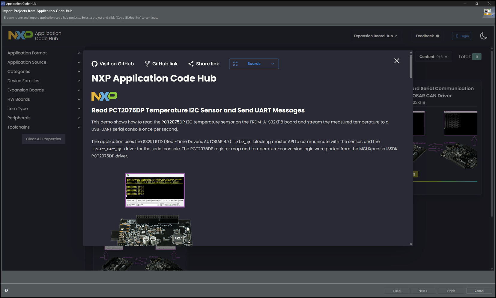
Figure 42 Details of the "Read PCT2075DP Temperature I2C Sensor and Send UART Messages" project
After reviewing the contents of the project to be imported, "Read PCT2075DP Temperature I2C Sensor and Send UART Messages," click "GitHub link," then click "Next >" to start cloning.
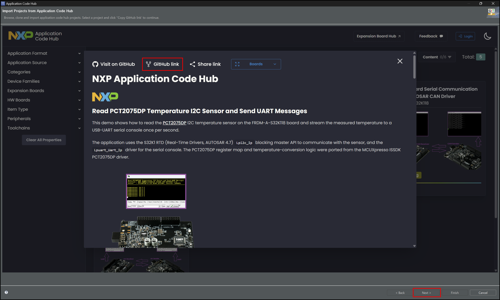
Figure 43 Project cloning started
Importing a project into S32 Design Studio
Import as an Eclipse project
In the import wizard, proceed by clicking "Next >" on the default settings unless otherwise specified. Select "Import existing Eclipse projects" and click "Next >", then select the project in the repository (FRDM_A_S32K118_I2C_Temp_UART), and finally click "Finish".
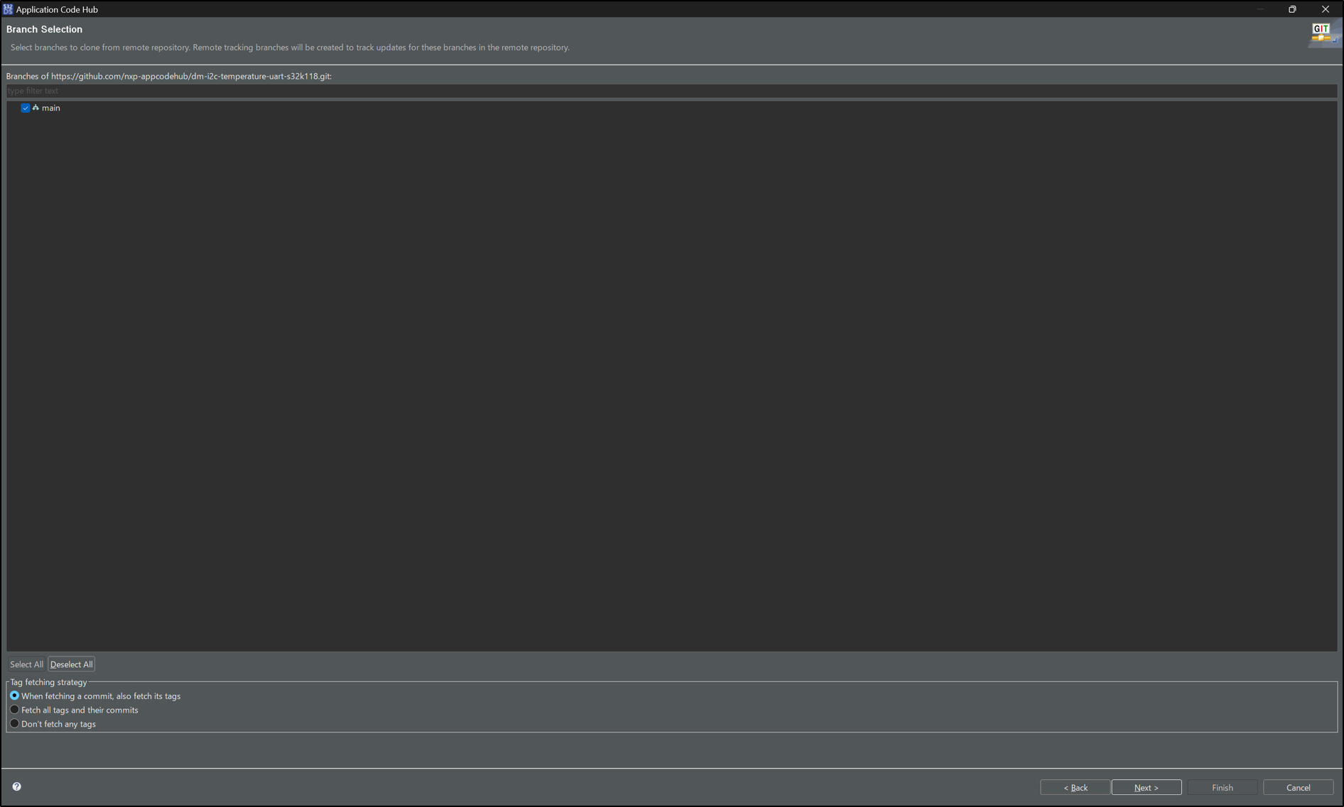
Figure 44 Branch Selection for Cloning
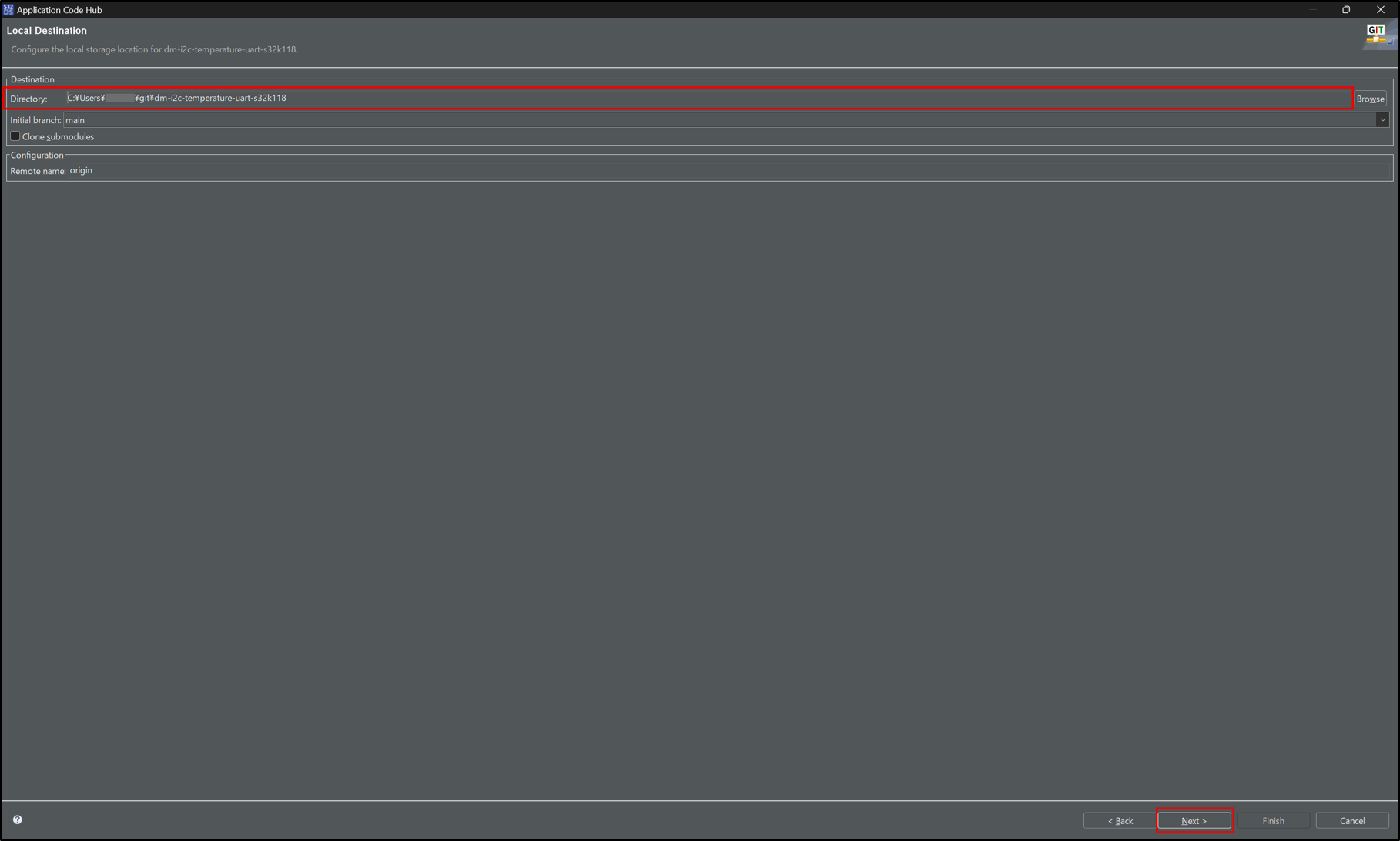
Figure 45 Specifying the clone destination (Local Destination)
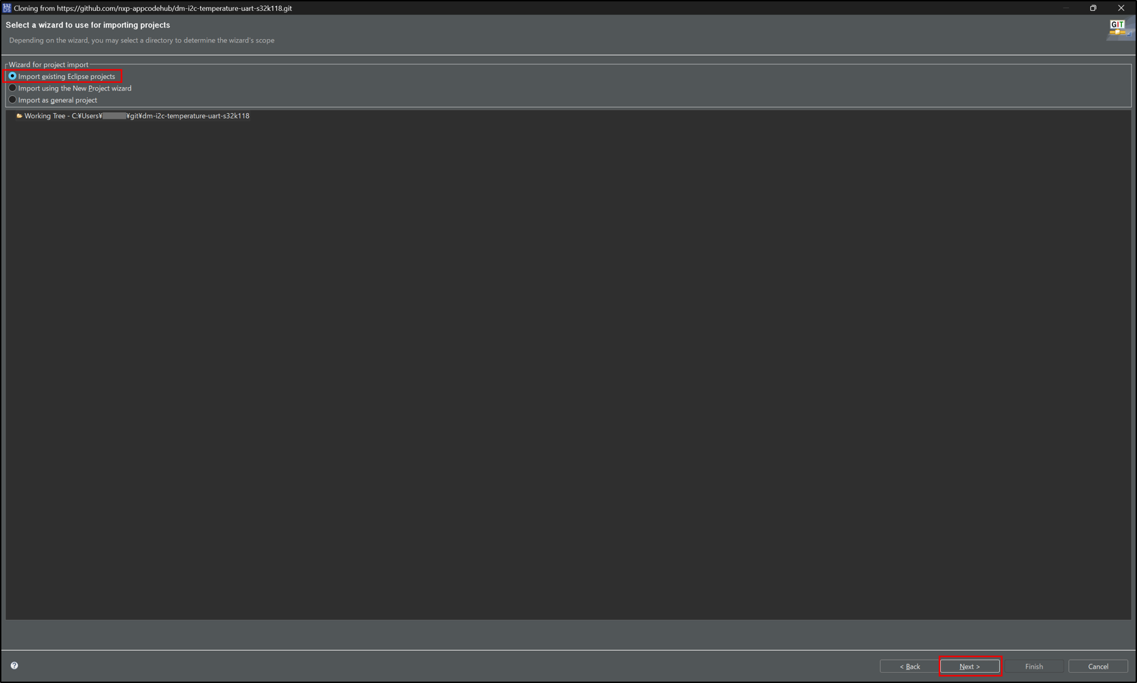
Figure 46 Import Wizard Selection (Import existing Eclipse projects)
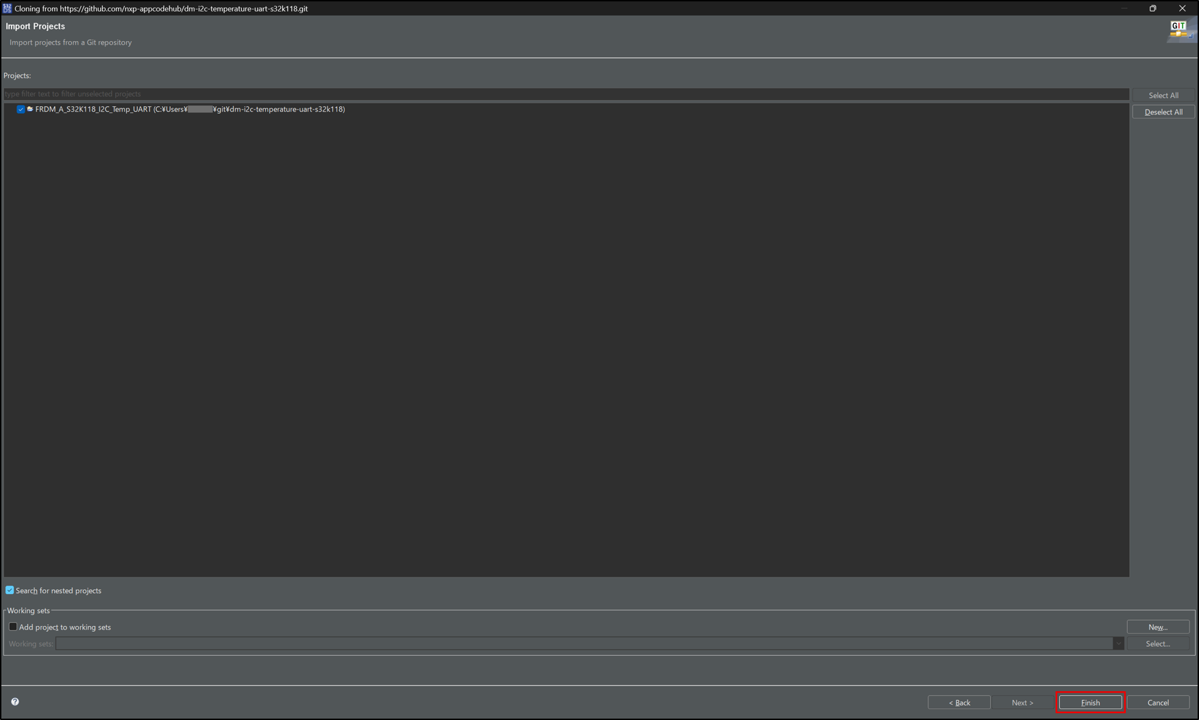
Figure 47 Confirmation and completion of the project to be imported (Finish)
The project will be added to the Project Explorer on the left.
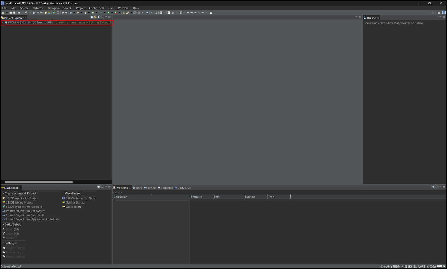
Figure 48 Projects added to Project Explorer
Note: Check the content from your browser.
The same information can also be viewed in a browser. Access to Application Code Hub (mcuxpresso.nxp.com/appcodehub) and search for "S32K118".
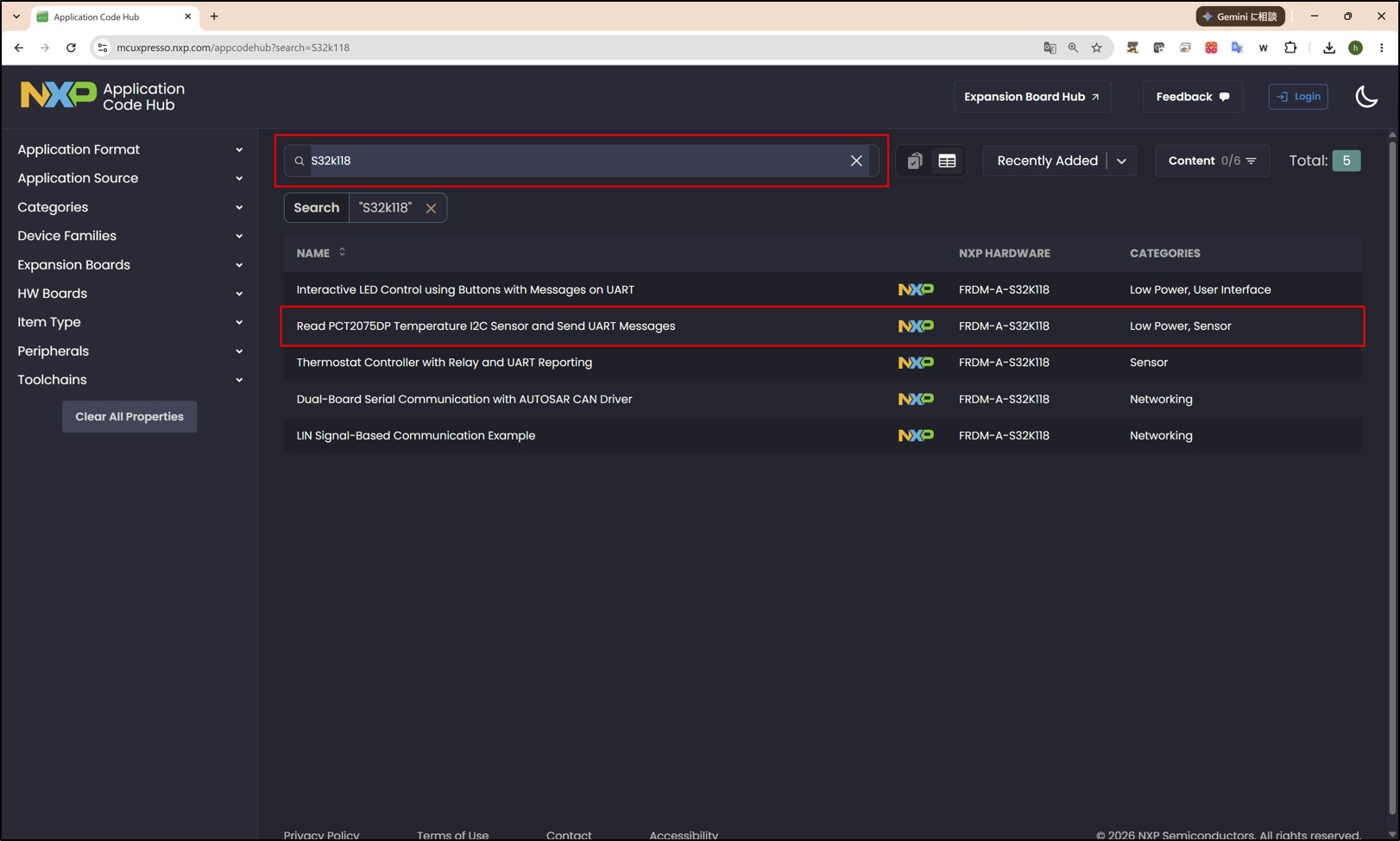
Figure 49 Sample code search in Application Code Hub (browser)
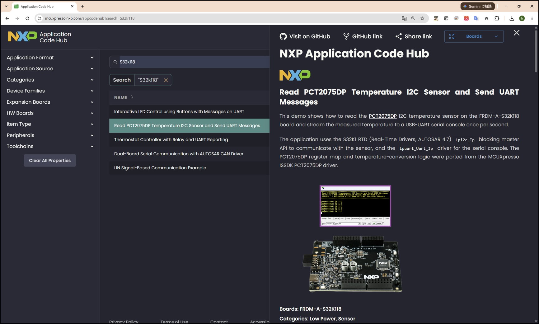
Figure 50: Explanation of the sample code (Read PCT2075DP Temperature I2C Sensor and Send UART Messages) (Browser)
Code generation and build
Update the code and build the project.
Right-click the project in Project Explorer and select "Update Code and Build Project". This will generate the configuration (Pins / Clocks / Peripherals) and update the source code, then build the project with the active configuration (e.g., Debug_FLASH).
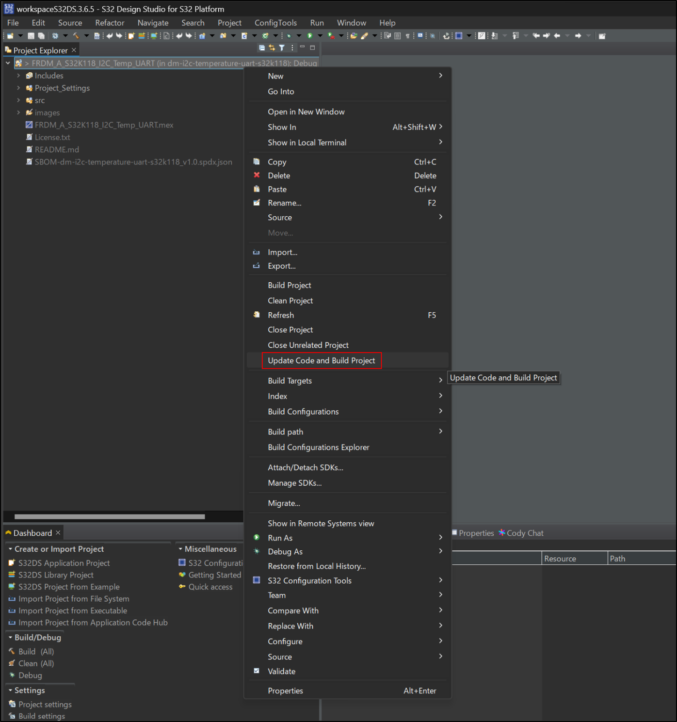
Figure 51 Update Code and Build Project (right-click menu)
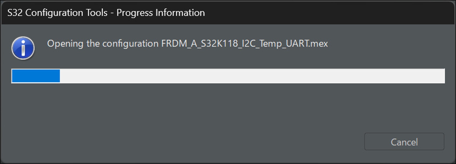
Figure 52 Configuration generation in progress
If you see "Build Finished. 0 errors" or similar in the Console, the build was successful.
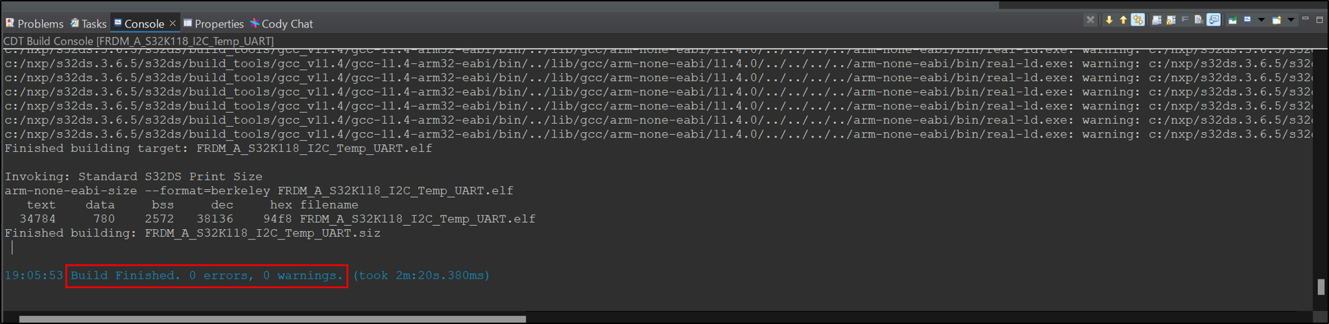
Figure 53 Build complete (Console: 0 errors, 0 warnings)
When you encounter build errors...
If your build does not complete with 0 errors, please check the following. Here are some common causes and solutions.
-
① If the RTD (Real-Time Drivers) are not installed or are of a different version, errors will occur during code generation and building if the version of the RTD referenced by the project does not match the RTD installed in S32 Design Studio. Please select and install the RTD using the Automotive Software Package Manager.
-
② Missing generated code files (Update Code not executed): If you build before generating the configuration, the expected header/source files (e.g., StandardTypes.h) will not be found, resulting in a "No such file or directory" error. Right-click on the project and select "Update Code and Build Project" (Figure 51) to complete code generation before building. *
Flash writing and debug execution
Open debug configuration
Open the "Run" → "Debug Configurations" menu. Select the debug configuration for this project and click "Debug".
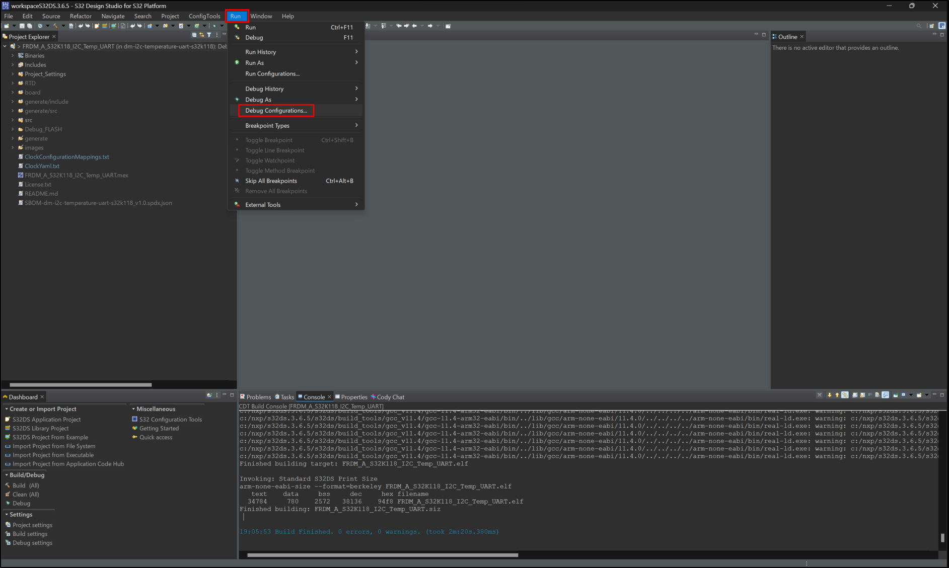
Figure 54 Open Debug Configurations (Run menu)
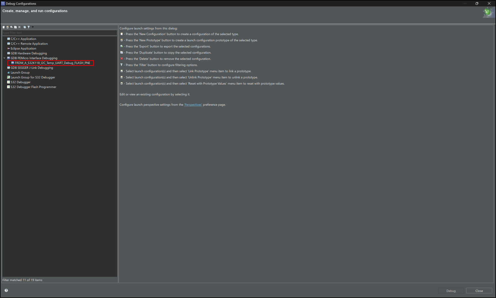
Figure 55 Debug Configurations (List of debug configurations)
When debugging is started with the FRDM-A-S32K118 connected via USB, an .elf file is written to the flash memory.
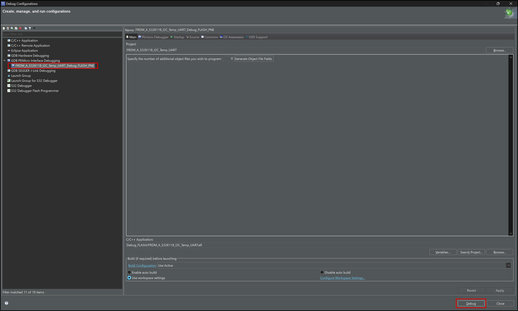
Figure 56 Debug configuration Main tab (running in Debug mode)
Click "Switch".
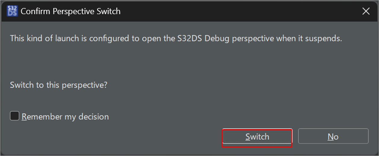
Figure 57 Confirm Perspective Switch (Click Switch)
Run the program and check the temperature.
When debugging is started, the program stops at the beginning of main().
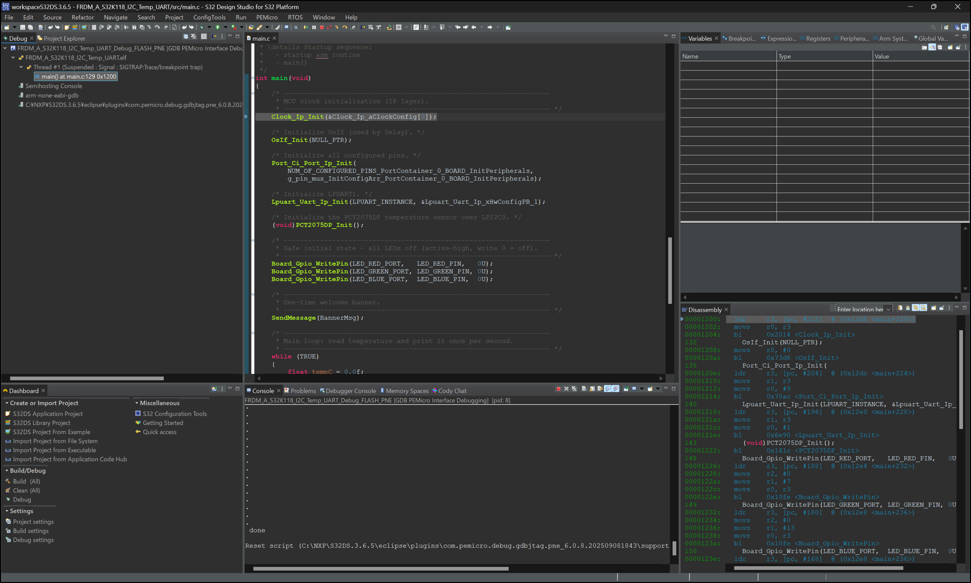
Figure 58: Stopped at the breakpoint in main()
Clicking the "Resume" button will execute the program.
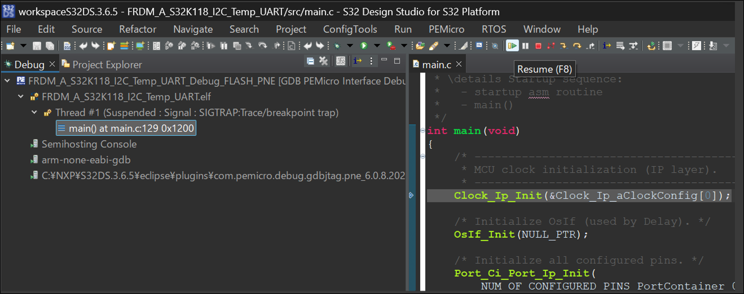
Figure 59 Resume button on the debug control toolbar
The temperature can be checked using terminal software. You can use any terminal software you prefer. In the diagram, Tera Term is used. Launch the terminal software, select "Serial," then select "OpenSDA - CDC Serial Port" from "Ports," and click "OK." The COM port number will vary depending on your PC.
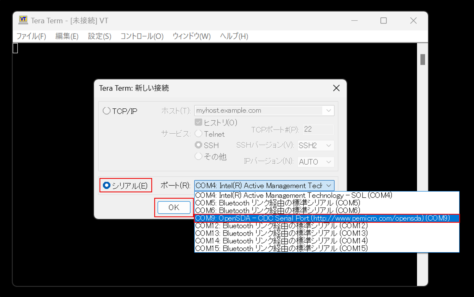
Figure 60 New connection in terminal software (select the serial port for OpenSDA)
Select "Settings" → "Serial Port" from the menu.
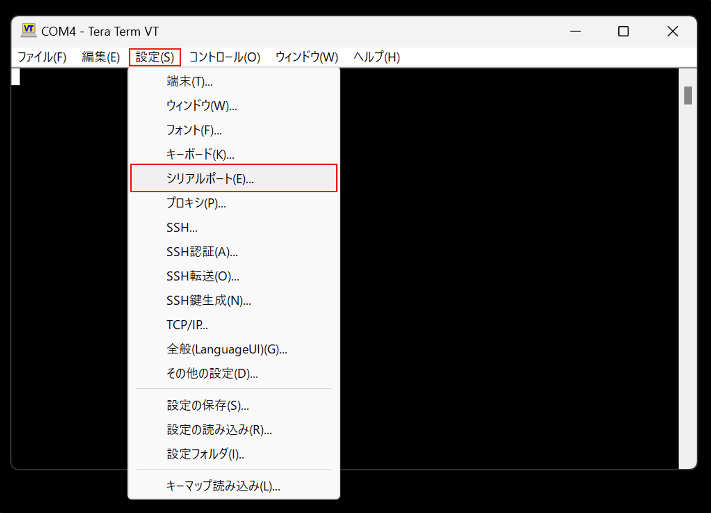
Figure 61 Terminal software settings menu (serial port)
Set "Speed" to 115200, "Data" to 8 bits, "Parity" to none, "Stop Bits" to 1 bit, and "Flow Control" to none, then click "Reconfigure Current Connection".
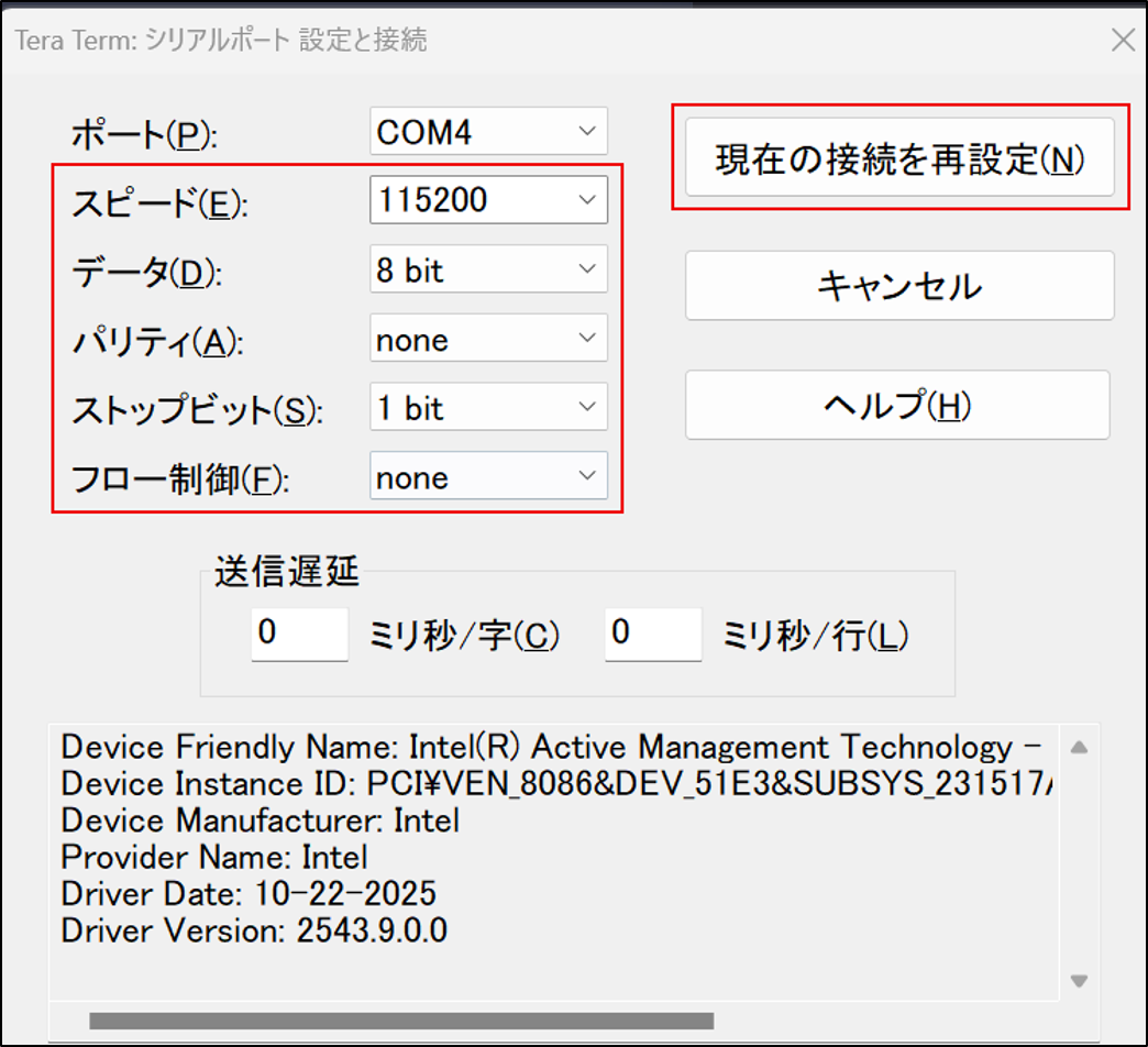
Figure 62 Serial port settings in terminal software
When the program is run, the temperature measured by TEMPERATURE SENSORS will be displayed in the terminal software every second.
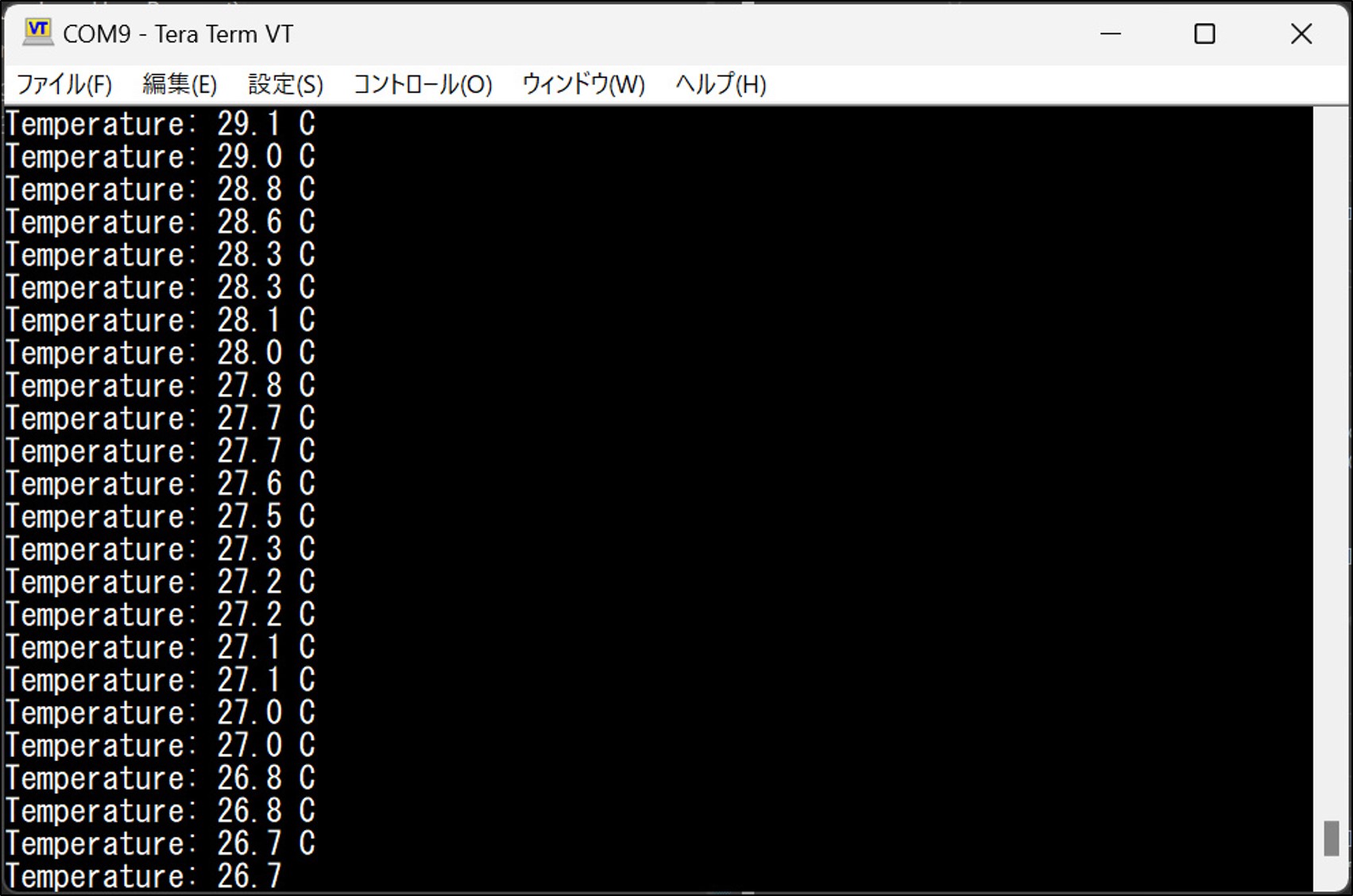
Figure 63 Temperature displayed in terminal software
Debugging will now end.
After confirming that it is working correctly, click the Terminate button (red square button) on the debug control toolbar to end debugging.
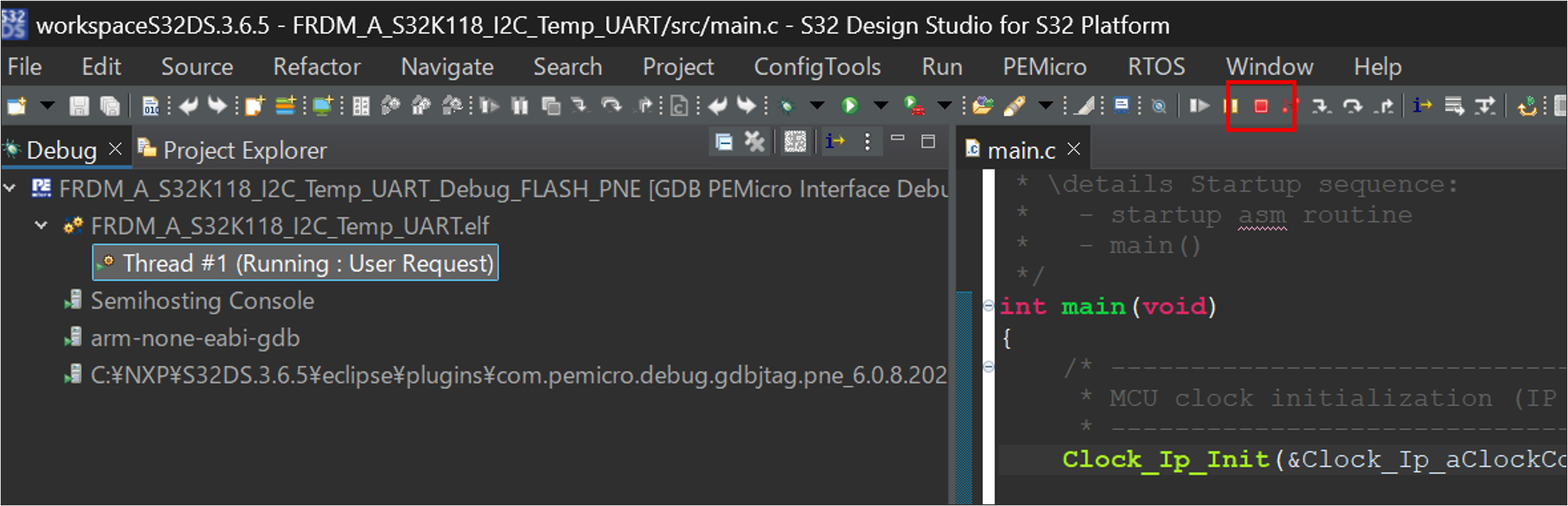
Figure 64 Debugging Termination
When you encounter a debugging error...
If you encounter any of the following errors, it may indicate that the evaluation board is not properly connected.
- Please ensure that the PC and the evaluation board are connected via a USB CABLES.
- In some cases, the connection may fail due to a broken USB CABLES, so please try replacing it with a different USB CABLES.
- The driver may not be working for some reason, so please restart your PC.
- If it still doesn't work, please try uninstalling and then reinstalling S32 Design Studio.
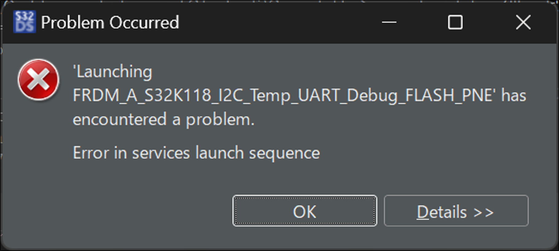
Figure 65 Example of a debug startup error (Problem Occurred)
Other points to note
The following two points should not occur if you follow the instructions in this book, but please note:
-
① If you create an empty project using "File" → "New" → "S32DS Application Project" and run it without connecting a debugger, a reset will occur. The "Debugger Console" setting in "I/O Support" is for performing input/output such as printf via the debugger. If you want to run it without connecting a debugger, select "No I/O" in "I/O Support" when creating the project.
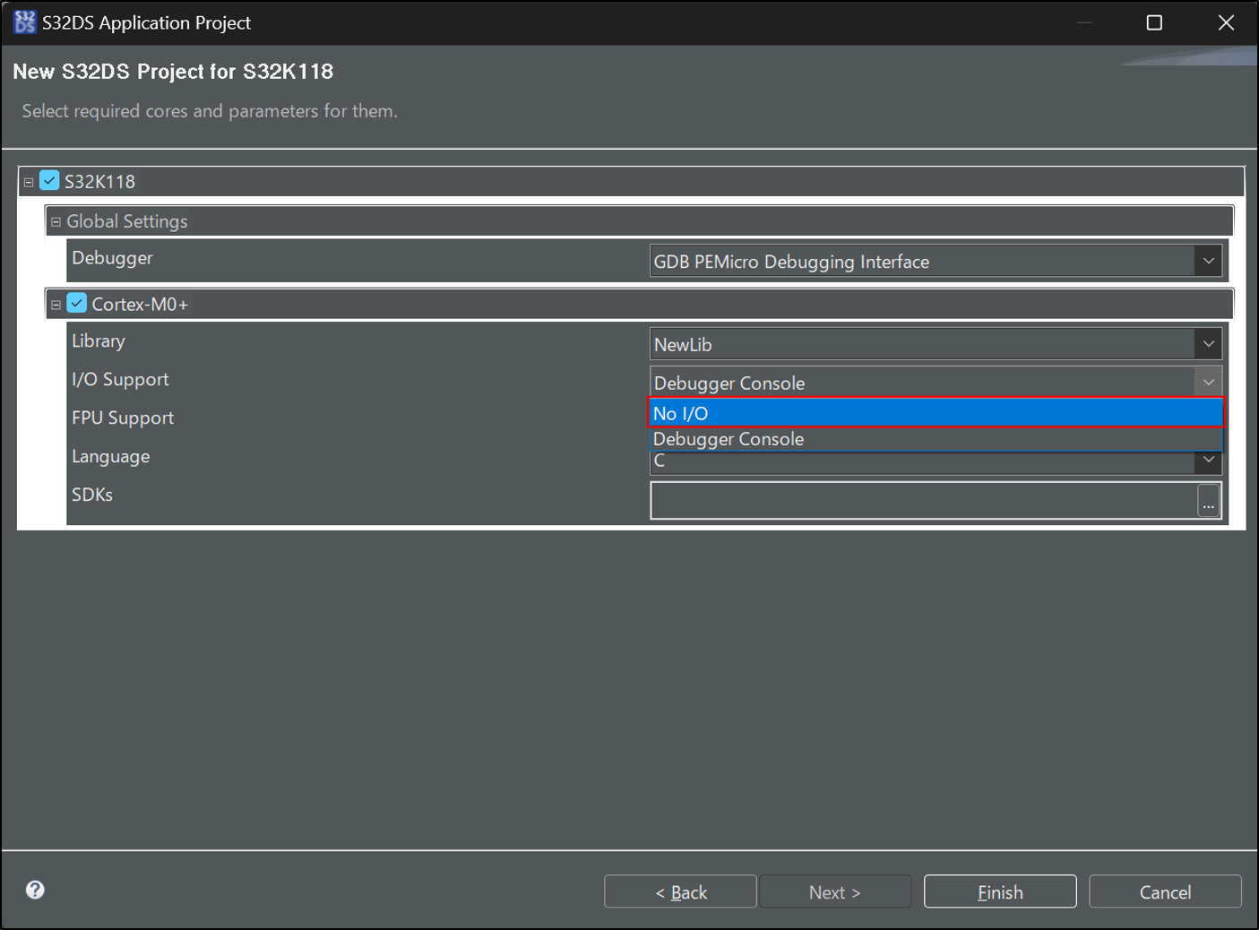
Figure 66 Selection of I/O Support when creating a project (No I/O)
-
② When using a USB Type-C to Type-A CABLES, the board's POWER SUPPLIES will not be turned off even if SWITCHES SW1 is set to Off. SW1 is SWITCHES that toggles the Configuration Channel (CC) line of the USB Type-C. The USB-C POWER SUPPLIES detects the board via the CC line and supplies power, but the CC line is a signal line that is only present on USB Type-C and not on USB Type-A. Therefore, the USB Type-A port continues to supply power regardless of the CC line. Connect the USB-C POWER SUPPLIES or the PC's USB-C port to the USB-C (PD compatible) CABLES as instructed in this manual.
Summary
In this book, we installed S32 Design Studio and RTD using the FRDM Automotive software bundle to set up the development environment for FRDM-A-S32K118. Furthermore, we verified that we could read the measured values from the PCT2075DP TEMPERATURE SENSORS via I2C and display them in terminal software via UART using sample code from the Application Code Hub.If you are interested, please feel free to Inquiry Nexty Electronics.
Related Info
Inquiry
Related Product Information
Startup Guide: Trying out the FRDM-A-S32K344
This guide explains everything from setting up the development environment for NXP's automotive development board "FRDM-A-S32K344" to building and running sample applications.
- NXP Semiconductors NV
- NEXT Mobility
Startup Guide: Trying out the FRDM-A-S32K312
This guide provides a clear explanation of everything from setting up the development environment for the NXP FRDM-A-S32K312 to building and debugging sample code.
- NXP Semiconductors NV
- NEXT Mobility
Overview of FRDM Automotive's evaluation board for automotive microcontrollers.
Introducing NXP's FRDM Automotive automotive, MCU evaluation board. Compatible with S32K/S32M, it efficiently supports everything from evaluation to prototyping and mass production development.
- NXP Semiconductors NV
- NEXT Mobility
Introducing NXP's Recommended Analog IC Products: The "Unseen Mainstays" Supporting ECU Development
This section showcases NXP's analog IC products for automotive ECUs, highlighting their role as components supporting peripheral functions such as sensors, RTCs, displays, communications, and POWER SUPPLIES.
- NXP Semiconductors NV
- NEXT Mobility

Introducing NXP's CAN TRANSCEIVER products with signal improvement (SIC)
NXP's SIC-equipped CAN TRANSCEIVER actively suppresses ringing on the transmitting side, stabilizing high-speed CANFD communications. It is software and pin compatible, allowing it to be replaced with existing designs, and is compliant with automotive standards.
- NXP Semiconductors NV
- NEXT Mobility

Introducing NXP's automotive LED DRIVER
Introducing NXP's automotive LED DRIVER. This product line supports constant voltage, constant current, high-precision PWM, and I2C/SPI, making it ideal for dimming multiple LEDs and displays.
- NXP Semiconductors NV
- NEXT Mobility
Link to Related Technical Columns

No need for an oscilloscope! High-precision time measurement using ARM-Cortex M DWT CYCCNT - A practical guide to minimized steps
This article provides an easy-to-understand explanation of the procedures and practical points for highly accurate time measurement on ARM Cortex-M using DWT CYCCNT without the need for external equipment.

Real-time AI tracking camera built with i.MX 93 - Achieving human tracking with NPU and servo motors
This document explains the procedure for building a camera that uses the i.MX 93 NPU and eIQ to perform face detection and track people in real time, from building a Yocto BSP to configuring PWM and using servo control.

A thorough explanation of the directories generated by bitbake | Essential for troubleshooting Yocto development
We will explain the structure and use of bitbake's tmp subdirectories (work, work-shared, deploy, etc.), as well as Yocto troubleshooting procedures using log checking and deb distribution.

Azure RTOS ThreadX Practical Guide: Practical Explanation of Task Management and Communication Functions
We will explain multitasking design and communication functions such as message queues in Azure RTOS (ThreadX).
First Steps with Azure RTOS: Creating a "Hello World" Project Using Azure RTOS
This article explains how to create, build, and debug a Hello World message using Azure RTOS (ThreadX) on the i.MX RT1170 evaluation board.

Building an i.MX Development Environment (Yocto Edition) | Technical Column
This article explains how to set up a Yocto development environment using NXP’s i.MX series. It covers hardware, preparation steps, and build procedures, helping you prepare to flash images on i.MX evaluation boards.