
- NXP Semiconductors NV
- NEXT Mobility
This book outlines the setup procedures for the NXP FRDM-A-S32K344 development board for automotive applications.
This section outlines the three essential steps for getting started, including supplementary information.
- Software Installation
- Connection method
- Building and running applications using Application Code Hub
- FRDM: This is the name of a development board provided by NXP, and it is pronounced "Freedom".
FRDM-A-S32K344 Overview
The FRDM-A-S32K344 is a development board equipped with NXP's automotive microcontroller S32K344 (Cortex-M7, 160MHz, 4MB Program Flash, 172-pin HDQFP).
It is equipped with CAN TRANSCEIVER (TJA1043), LIN TRANSCEIVER (TJA1022), an accelerometer (FXLS8964), TEMPERATURE SENSORS (P3T1750), and the FS26 system base chip (SBC).
It also features user-accessible RGB LEDs (red/green/blue), two user-accessible push buttons, and a RESET button. Furthermore, it supports Arduino header-compatible pinouts, allowing for the connection and evaluation of various expansion boards.
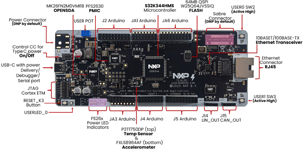
Figure 1 FRDM-A-S32K344
Prerequisites
Please ensure that the following three prerequisites are met.
- I already have an NXP account.
- I possess FRDM-A-S32K344.
- I own a PC that supports USB-C.
Software Installation
Open "Getting Started with the FRDM Automotive S32K344 Development Board for General Purpose" in the documentation section of the "FRDM S32K344 Development Board for General Purpose" page on the NXP website.
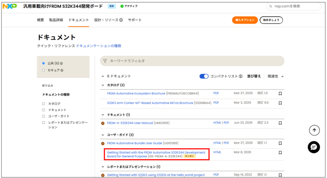
Figure 2: Development board page for the general-purpose automotive FRDM S32K344.
After reviewing "1. Package Contents" in the Start Guide for the General-Purpose Automotive FRDM S32K344 Development Board, proceed to "2. Software Acquisition".
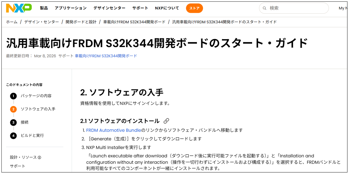
Figure 3: Start Guide Page (2. Software Installation)
Click the link to go to the In-Vehicle Software Package Manager.
First, a sign-in screen will appear, so please sign in following the steps below (you can skip this step if you are already signed in).
Sign in to your NXP account
Enter the email address you registered and click "Continue".
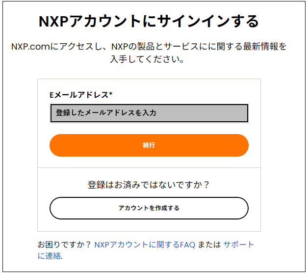
Figure 4: Sign-in screen (email address)
Next, enter your password and click "Sign In".
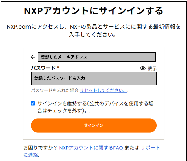
Figure 5 Sign-in screen (password)
*If you have enabled multi-factor authentication in your NXP account settings, you will need to enter an additional passcode.
Bundle generation and download
The In-Vehicle Software Package Manager will open.
On the left side, under DEVICES, check the box for General-Purpose MCUs > S32K3.
On the right side, under SDK, BUNDLES AND USE CASES, check the box for "FRDM Automotive Board Installation Package," and then click "GENERATE BUNDLE INSTALLER" at the bottom of the screen.
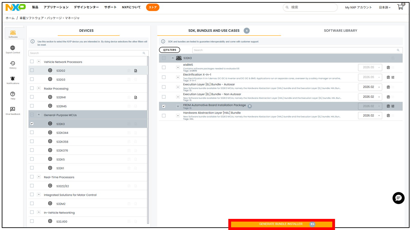
Figure 6: Screen for selecting the bundle to install.
In "Review package selection," review and select the packages to add to the bundle. In this example, we select Real-Time Drivers 7.0.0 QLP03 D2512 and S32 Design Studio and Configuration Tools 3.6.5 D2511, and click "NEXT" (FreeMASTER, FreeRTOS, LIN Stack, TCP/IP Stack, etc. are also available as selections).
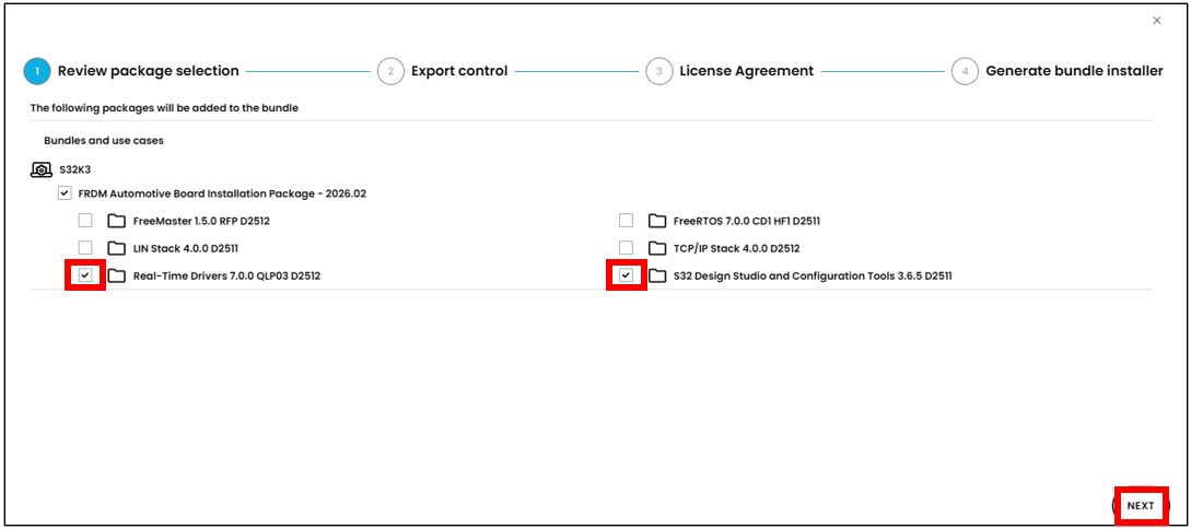
Figure 7 REVIEW PACKAGE SELECTION screen
In "Export control," enter the product/project type (e.g., Automotive) and application (e.g., development and evaluation of in-vehicle ECUs), and then click "SUBMIT EXPORT CONTROL."
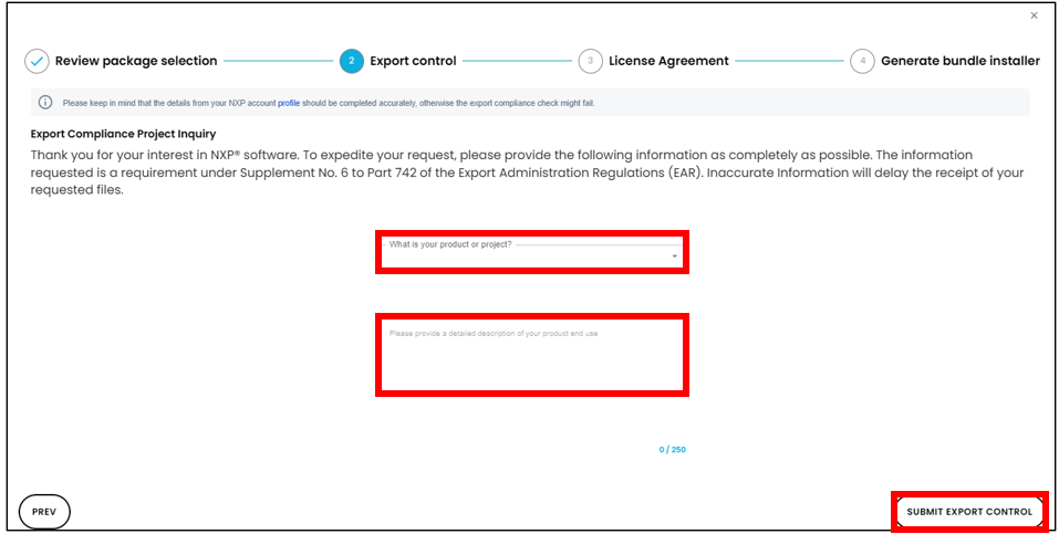
Figure 8 EXPORT CONTROL screen (product/project type and application are indicated)
Once you see the message "The following packages have passed export control checks." and the packages you selected in "Review package selection" are listed, click "NEXT".
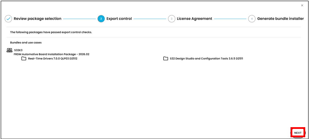
Figure 9 EXPORT CONTROL screen (Export control check passed)
Read the entire "License Agreement" and click "I ACCEPT THE TERMS OF THE LICENSE AGREEMENT" at the bottom of the page (you cannot click it until you scroll all the way down).
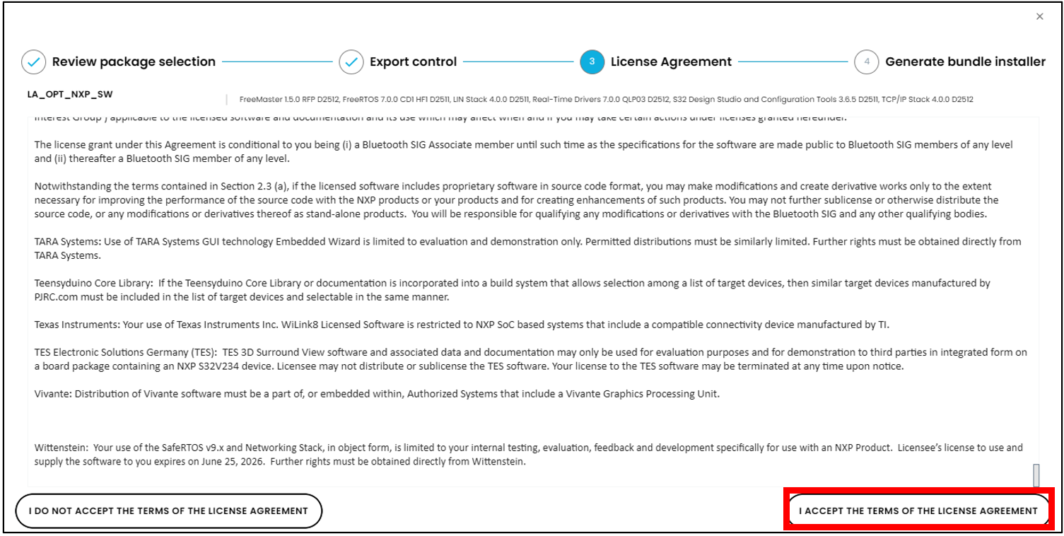
Figure 10 LICENSE AGREEMENT screen
Click "DONE" in "Generate bundle installer".
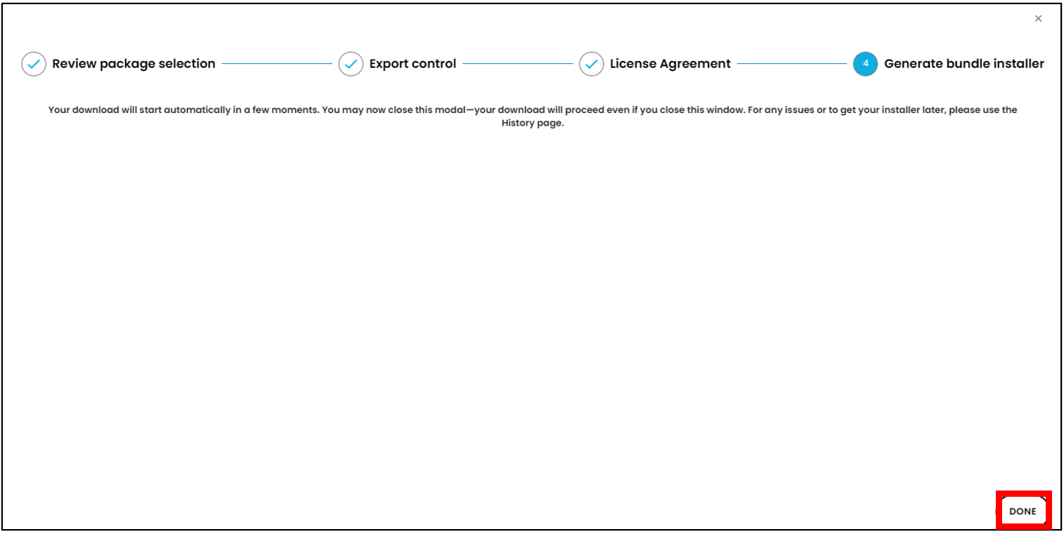
Figure 11 GENERATE BUNDLE INSTALLER screen
After a short while, the download will start automatically, and "NXP_Multi_Installer_XX.XX.XX.XXXXXX_setup.exe" and "NXP_Multi_Installer_XX.XX.XX.XXXXXX_User_Manual.pdf" will be saved to your PC's "Downloads" folder.
*The XX.XX.XX.XXXXXX listed here represents the date and time of download.

Figure 12: The "Downloads" folder on your PC
Installation using NXP Multi Installer
When you run the executable file (NXP_Multi_Installer_XX.XX.XX.XXXXXX_setup.exe) downloaded in the previous chapter, the "Welcome to the NXP Multi Installer XX.XX.XX.XXXXXX Setup Wizard" will be displayed. Click "Next >".
*The executable file has a limited usage time, and after this time (2 hours), the executable file will no longer be usable. Please proceed with the installation as soon as possible after performing "Bundle Generation and Download" (if the usage time has expired, please perform "Bundle Generation and Download" again to download a new executable file).
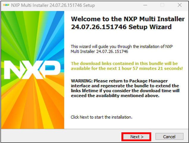
Figure 13: WELCOME TO THE NXP MULTI INSTALLER SETUP WIZARD screen (normal operation)
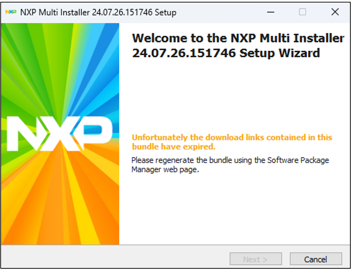
Figure 14 WELCOME TO THE NXP MULTI INSTALLER SETUP WIZARD screen (in case of error)
The "License Agreement" will be displayed. Review the contents and click "I Agree".
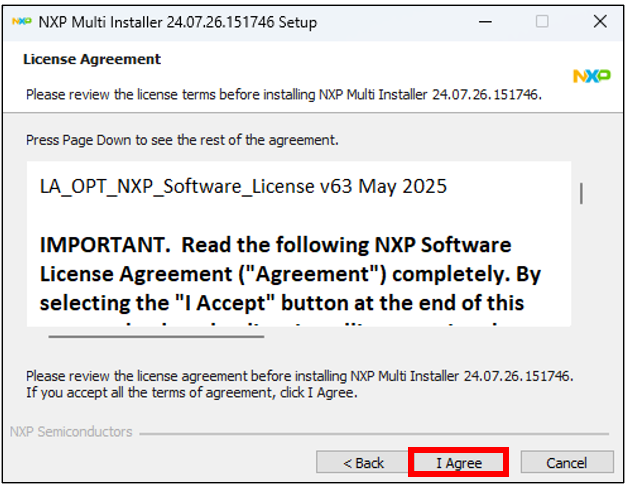
Figure 15 LICENSE AGREEMENT screen
The "Choose components" screen will appear. Click "Next >".
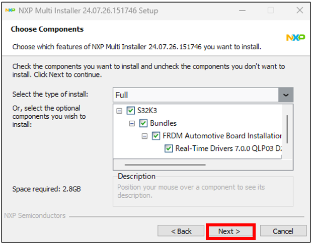
Figure 16 CHOOSE COMPONENTS screen
The "Choose Download Location" screen will appear. Set the folder where you want to download the file (the default is the same location as the executable file). Click "Next >".
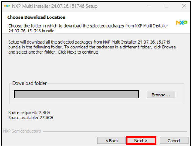
Figure 17 CHOOSE DOWNLOAD LOCATION screen
The "Ready to Download the Packages" screen will appear. Click "Launch executable after download" and "Installation and configuration without any interaction," then click "Download." This will install the FRDM bundle and all available components together.
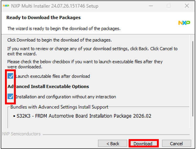
Figure 18 READY TO DOWNLOAD THE PACKAGES screen
The "Installation" process will begin.
*This process connects to NXP's download server and downloads the package. Please note that Access via a proxy server may cause the download to fail.
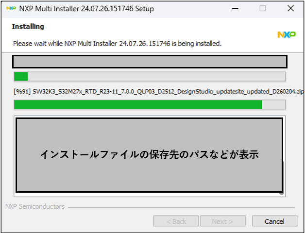
Figure 19 INSTALLING screen
Once the installation is complete, "Advanced Configuration" will open. Confirm that "Completed" is displayed, and then click "Next >".
*The log will contain "[FAILED]", but this is not a problem as FreeMASTER was not downloaded this time. We will proceed to the next step.
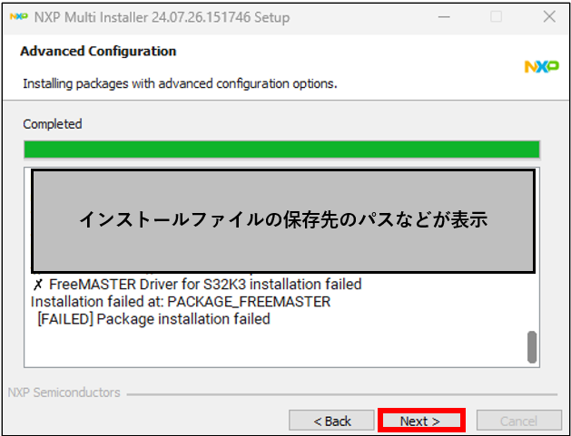
Figure 20 Advanced Configuration Screen
The "Completing the NXP Multi Installer XX.XX.XX.XXXXXX Setup Wizard" will open. Click "Finish" to complete the installation.
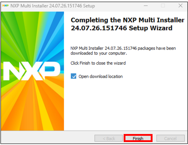
Figure 21 Completing the NXP Multi Installer Setup Wizard screen
Connection method
Proceed to "3. Connection" in the Start Guide for the General-Purpose Automotive FRDM S32K344 Development Board.
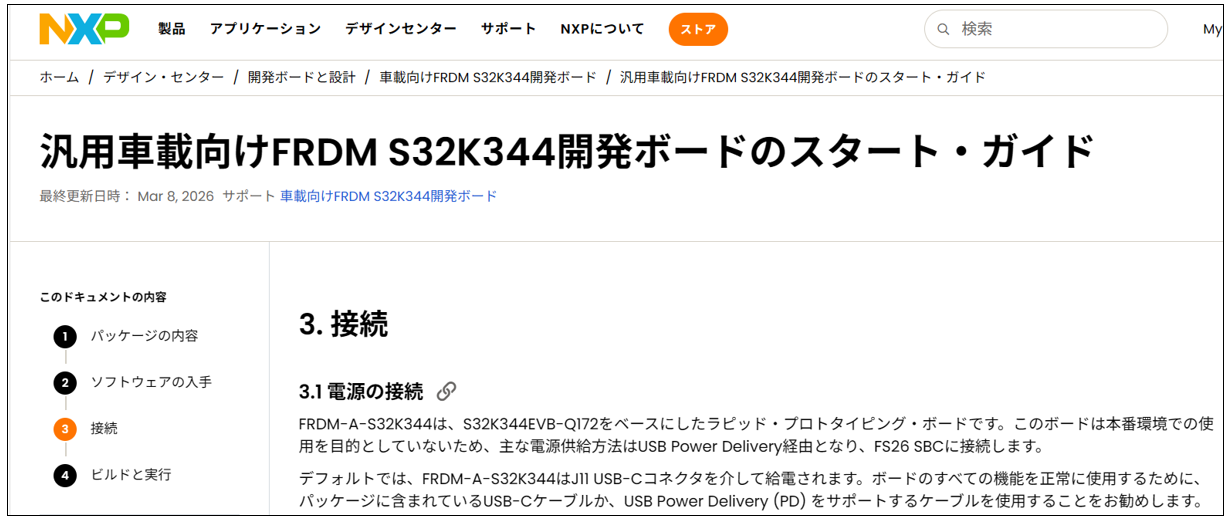
Figure 22 Start Guide Page (3. Connection)
The FRDM-A-S32K344 is powered via a USB-C CONNECTORS. To ensure all board functions work correctly, it is recommended to use the included USB-C CABLES or CABLES that supports USB Power Delivery (PD). Using a non-compliant CABLES may limit the current supplied and degrade performance.
Similarly, to properly power the board, we recommend using a USB-C PD compatible POWER SUPPLIES, such as a USB-C PD CHARGERS or a USB-C compatible laptop.
Startup sequence
1. Connect the USB-C CABLES connected to your PC to the J11 CONNECTORS to power the development board.
2. To POWER SUPPLIES on the board, change the position of SWITCHES SW5 to setting 2-3.
3. Verify that all POWER SUPPLIES LEDs on the development board are lit.
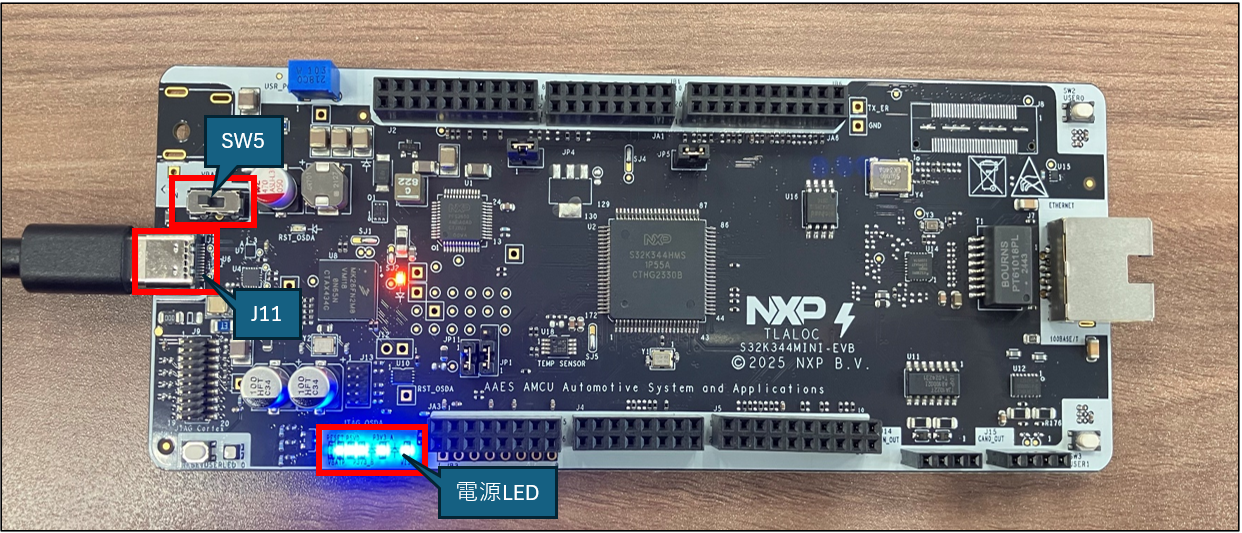
Figure 23 FRDM-A-S32K344 at startup
Building and running applications
Proceed to "4. Build and Run" in the Start Guide for the General-Purpose Automotive FRDM S32K344 Development Board.
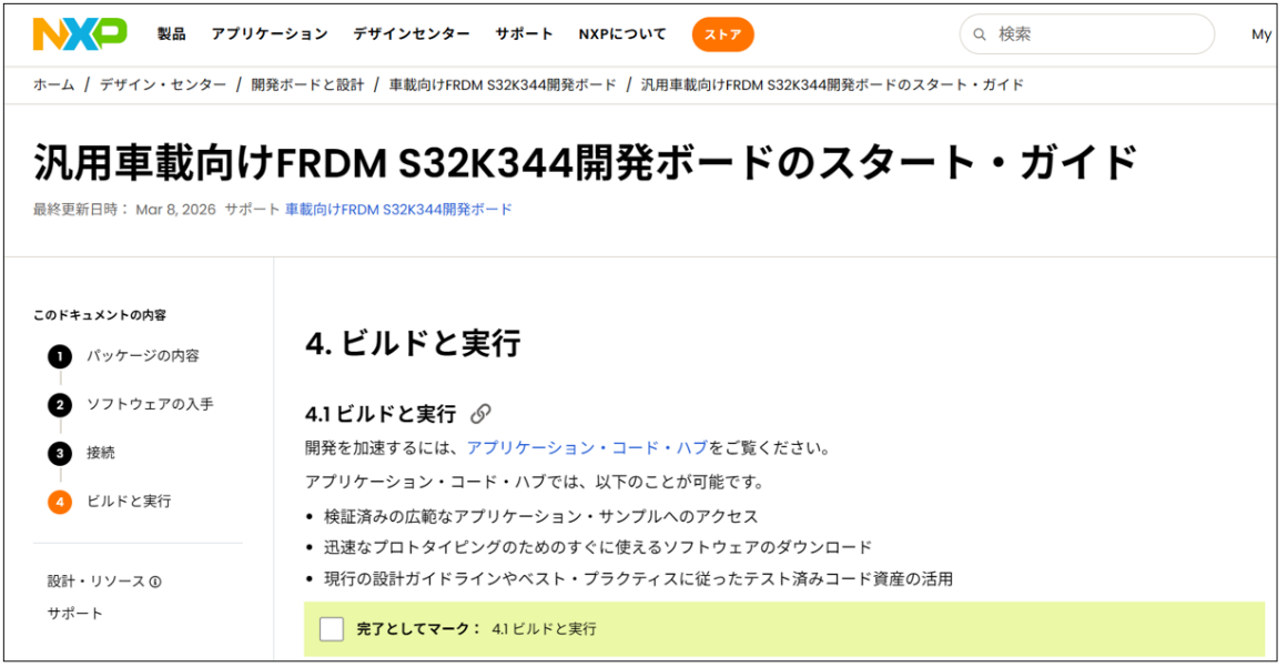
Figure 24 Start Guide Page (4. Build and Run)
Connect and power on the FRDM-A-S32K344 according to the procedure in the previous chapter.
Launching S32 Design Studio for S32 Platform 3.6.5
Click on the S32 Design Studio for S32 Platform 3.6.5 file created on your desktop. A "Select a directory as workspace" window will open; create a workspace and click "Launch" (the default location is within the "Users" folder on your PC).
*Please do not use the following paths as workspace paths. This may cause problems.
- Paths containing Japanese characters (full-width characters)
- Long/deep paths exceeding 200 characters
- Paths under cloud storage such as OneDrive and Google Drive
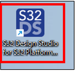
Figure 25 Desktop screen
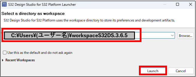
Figure 26 SELECT A DIRECTORY AS WORKSPACE screen
When you launch S32 Design Studio for S32 Platform, "S32DS Extensions and Updates" will open, so click "Cancel".
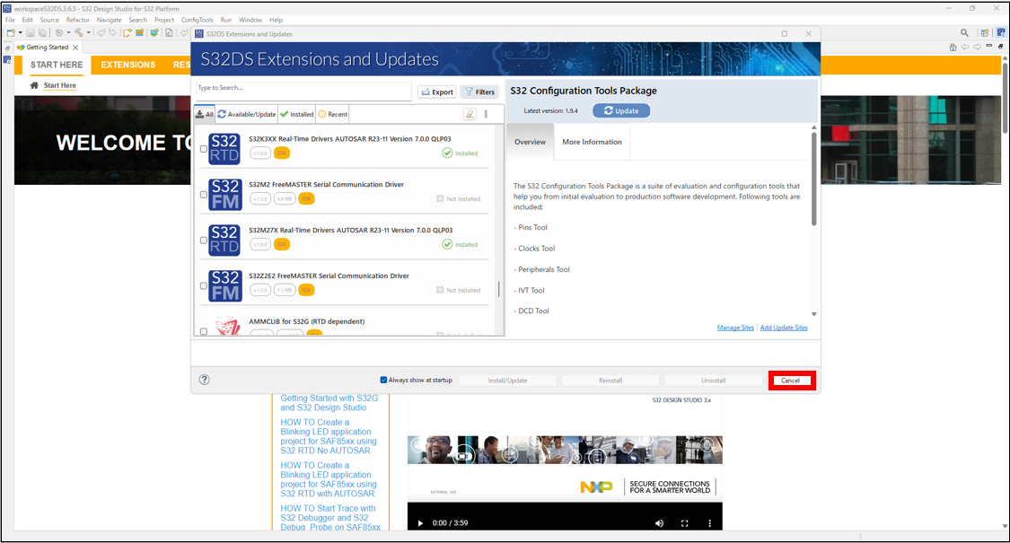
Figure 27 S32DS EXTENSIONS AND UPDATES screen
Next, click the "×" to close the "WELCOME TO S32 DESIGN STUDIO IDE" screen.
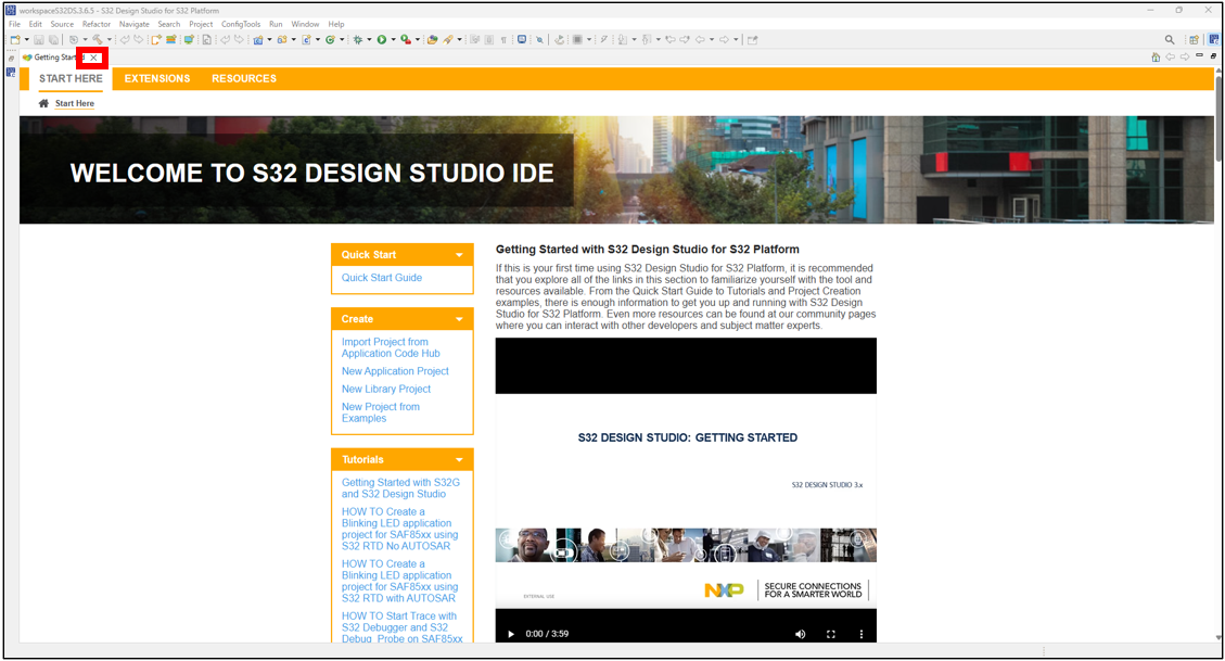
Figure 28 WELCOME TO S32 DESIGN STUDIO IDE screen
Importing an application
Clicking "Import Projects from Application Code Hub" in the bottom left corner will open NXP's "Application Code Hub" (you can also view the contents by Access https://mcuxpresso.nxp.com/appcodehub from your browser).
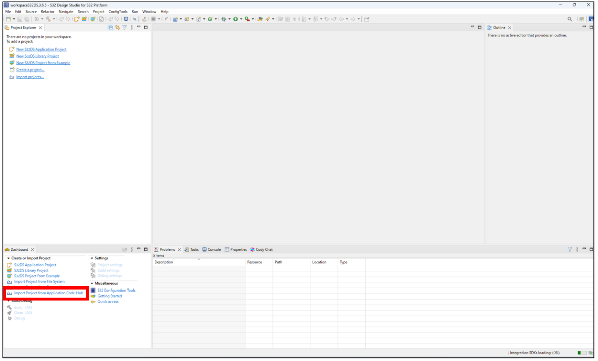
Figure 29: S32 DESIGN STUDIO FOR S32 PLATFORM 3.6.5 startup screen
By entering "S32K344" and searching, you can find applications for FRDM-A-S32K344. In this example, we will use "GPIO Blinking LED Demo for FRDM-A-S32K344" to build, run, and verify its operation.
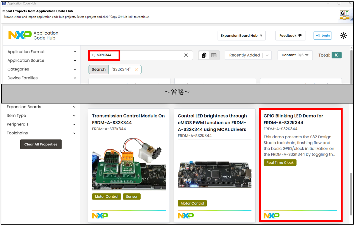
Figure 30 APPLICATION CODE HUB screen
Click on "GPIO Blinking LED Demo for FRDM-A-S32K344" and then click on the "GitHub link" on the NXP Application Code Hub.
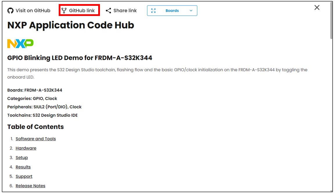
Figure 31 NXP APPLICATION CODE HUB screen (GPIO BLINKING LED DEMO FOR FRDM-A-S32K344)
Click "Next >" in the bottom right corner.
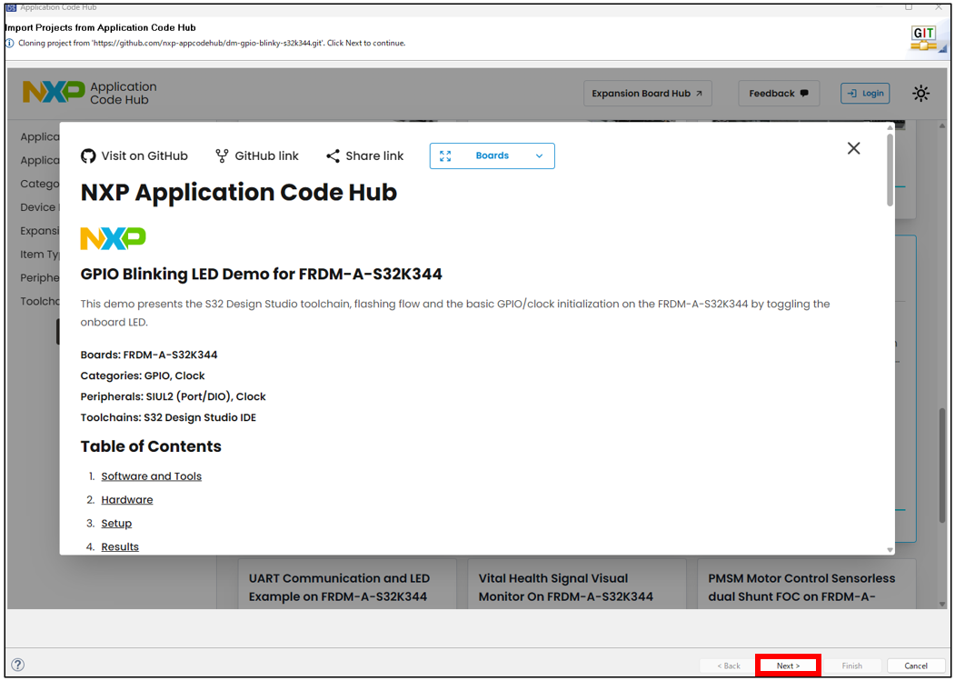
Figure 32 WELCOME TO S32 DESIGN STUDIO IDE screen
The "Branch Selection" screen will appear. Select "main" and check the box for "When fetching a commit, also fetch its tags". Click "Next >".
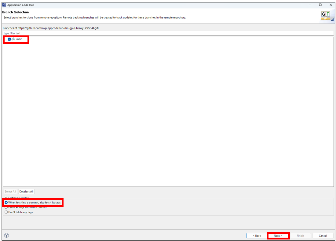
Figure 33 BRANCH SELECTION screen
The "Local Destination" will be displayed. Set the "Directory" to its default settings and click "Next >".
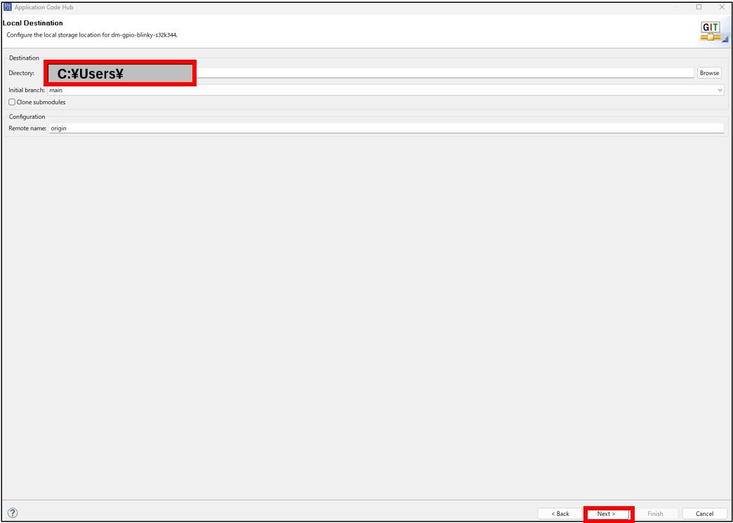
Figure 34 LOCAL DESTINATION screen
The "Select a wizard to use for importing projects" screen will appear. Select "Import existing Eclipse project" and click "Next >".
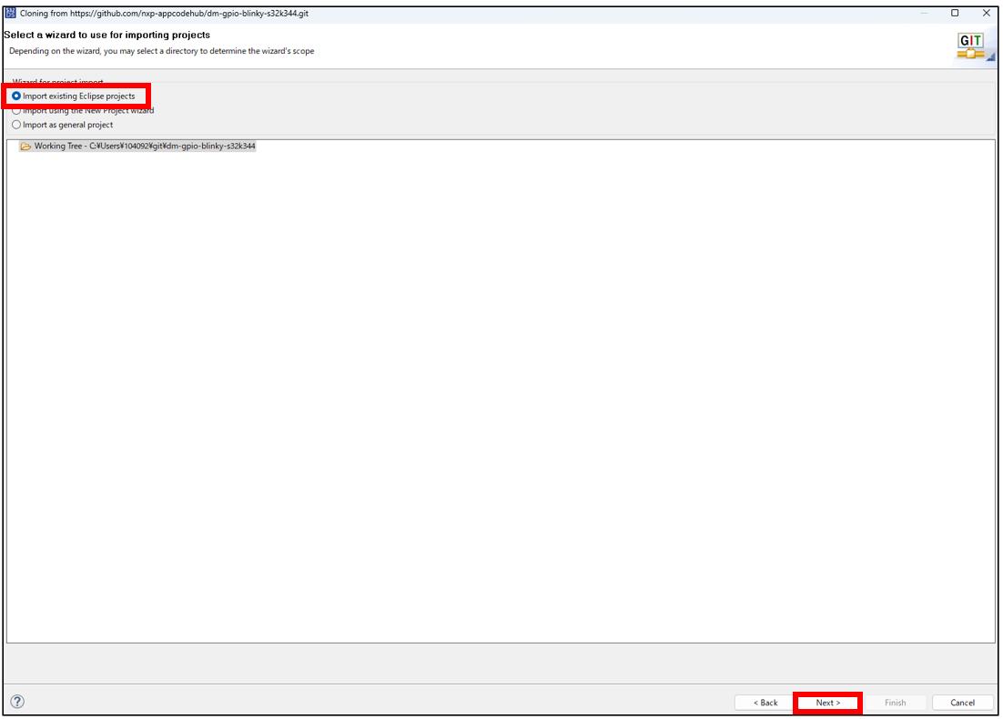
Figure 35 LOCAL DESTINATION screen
The "Import Projects" window will appear. Click "Finish".
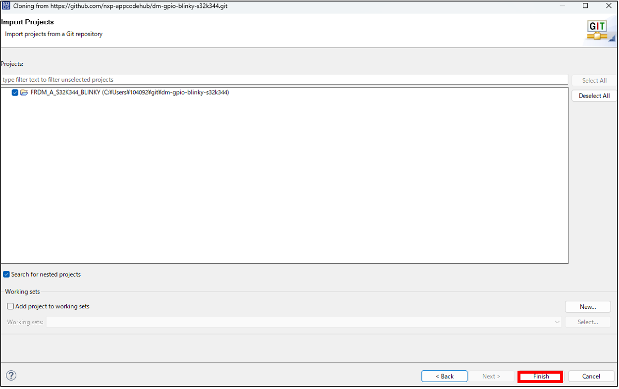
Figure 36 IMPORT PROJECTS screen
Please ensure that the source code for "GPIO Blinking LED Demo for FRDM-A-S32K344" has been imported.
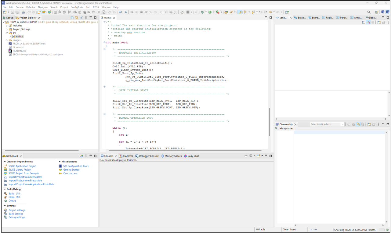
Figure 37 Imported screen
Build and Debug
In the previous chapter, we will build and debug the application that we imported. Step-by-step execution or run the application will become available, allowing you to verify its operation on the development board.
*The FRDM-A-S32K344 has an onboard debugger, so you do not need to prepare a separate debugger.
Right-click the project in the Project Explorer and click "Update code and build Project". This will generate pin, clock, and peripheral settings and update the source code.
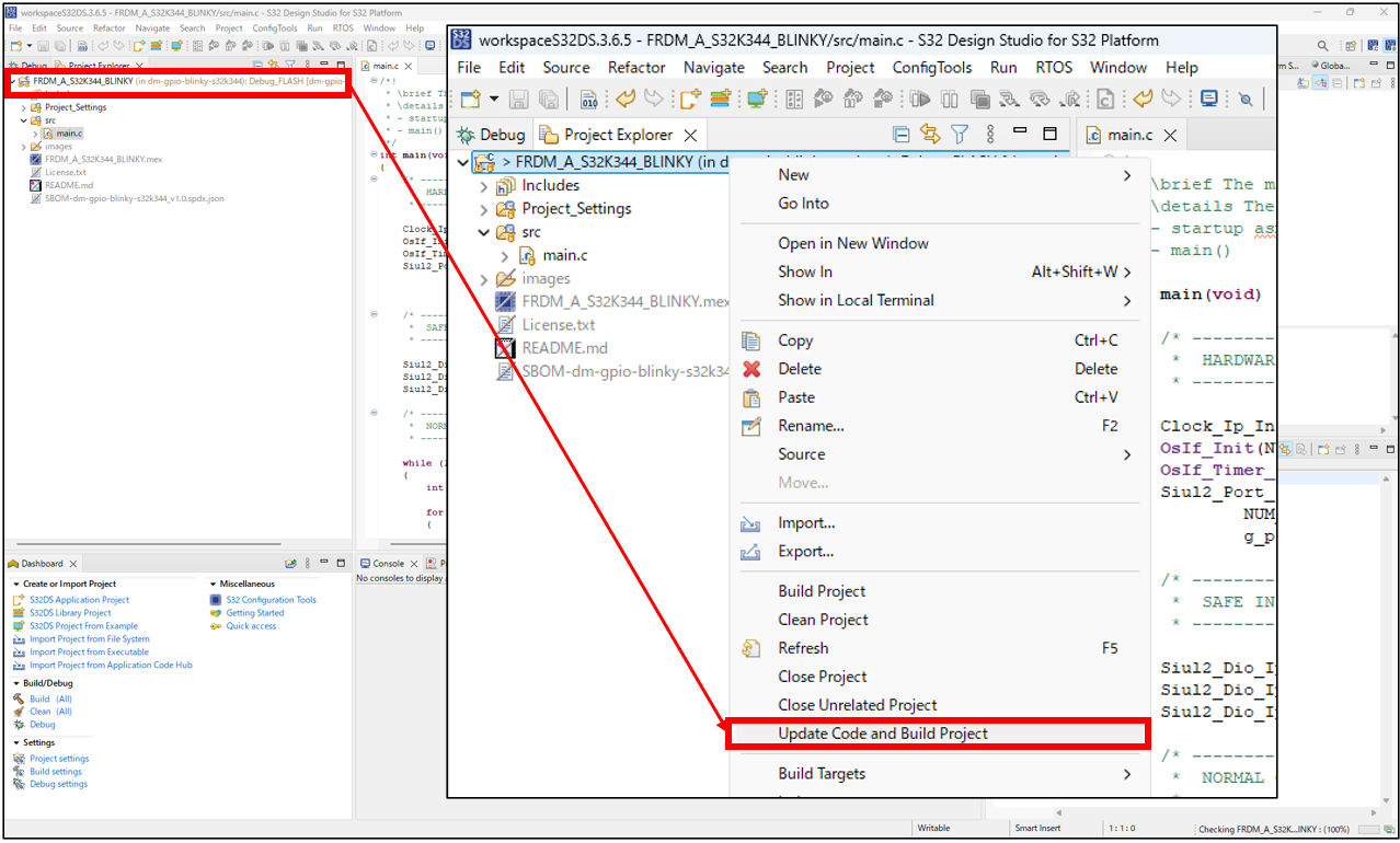
Figure 38 UPDATE CODE AND BUILD PROJECT selection screen
The build will be performed using the active configuration (e.g., Debug_FLASH). Check the "Console" screen to confirm that the build was successful. If the build completes successfully, a *.elf file will be generated.
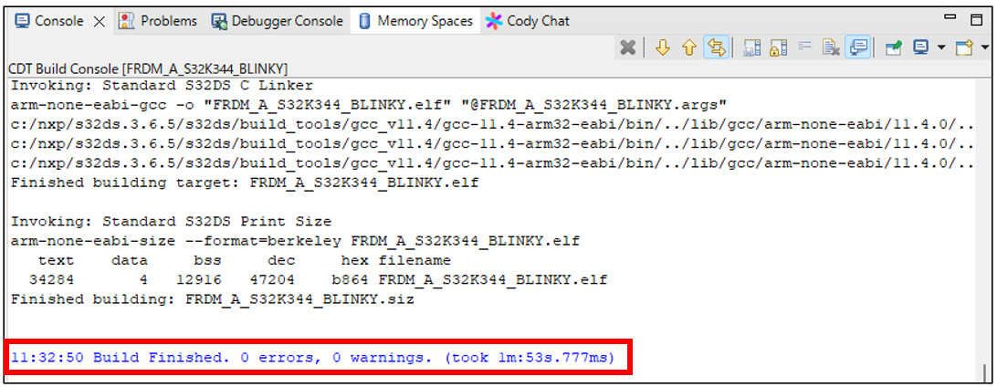
Figure 39 CONSOLE screen
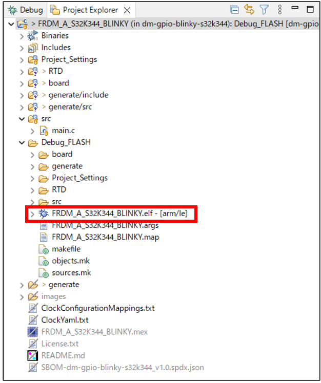
Figure 40 Project Explorer screen
Click the ▼ to the right of the [Debug] button and then click "Debug Configurations…".
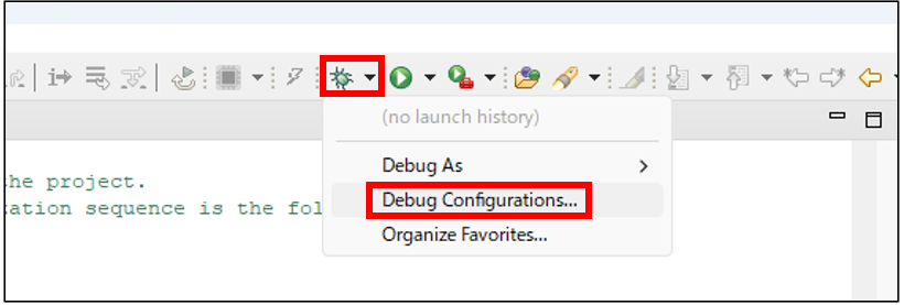
Figure 41 DEBUG button
The "Debug Configurations" window will appear. Select "FRDM_A_S32K344_BLINKY_Debug_FLASH_PNE" on the left and click "Debug".
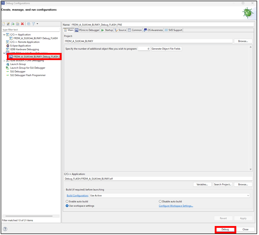
Figure 42 DEBUG CONFIGURATIONS screen
The "Confirm Perspective Switch" window will appear. Click "Switch" to switch to the Debug window.
*The development board must be connected during debugging. If it is not connected, an error will occur during the startup sequence.
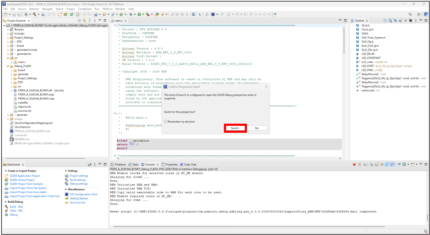
Figure 43 CONFIRM PERSPECTIVE SWITCH screen (normal operation)
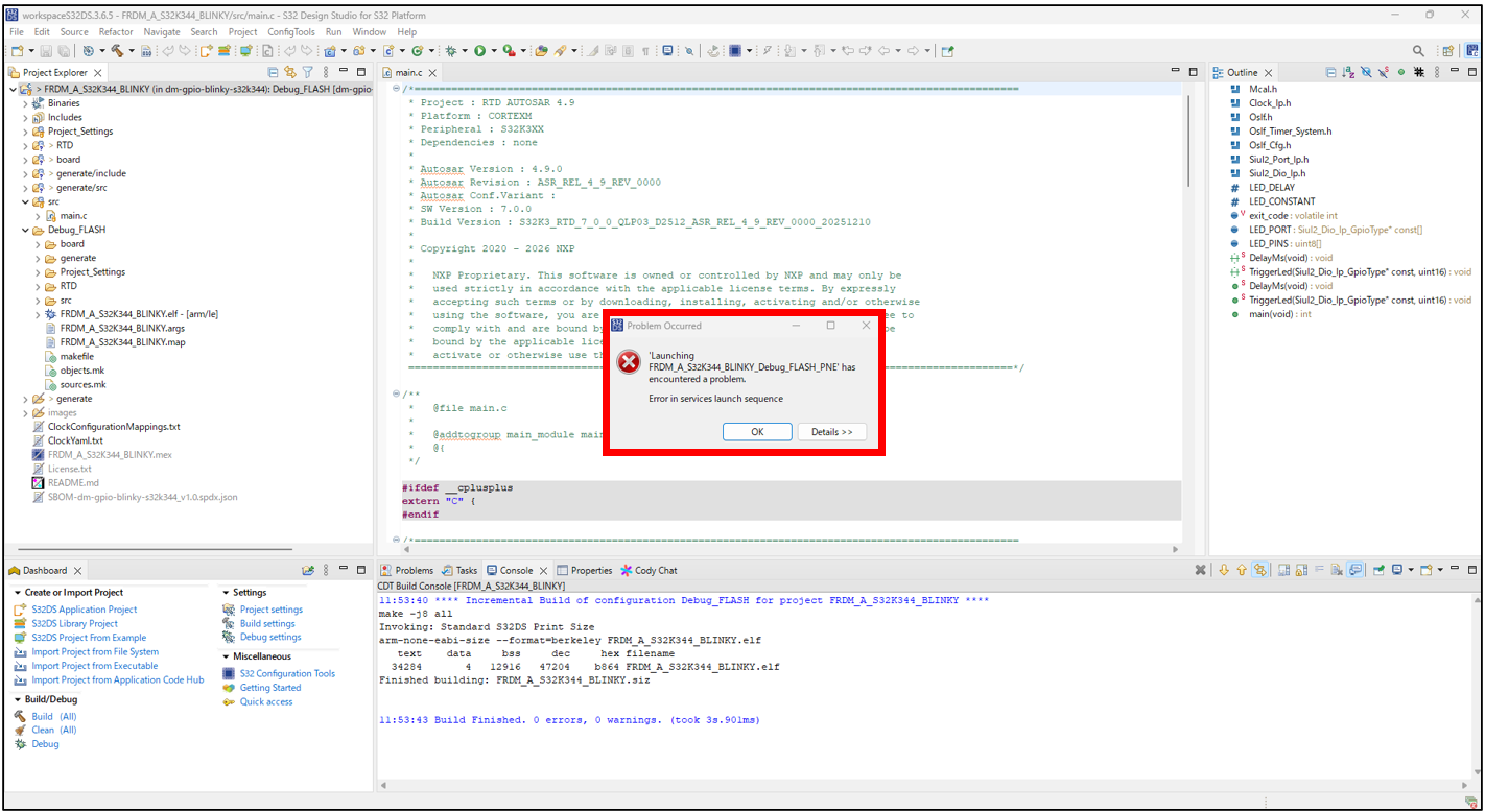
Figure 44 PROBLEM OCCURRED screen (when an error occurs)
The Debug window will open. Please click the Step Execution or Run button to check the operation.
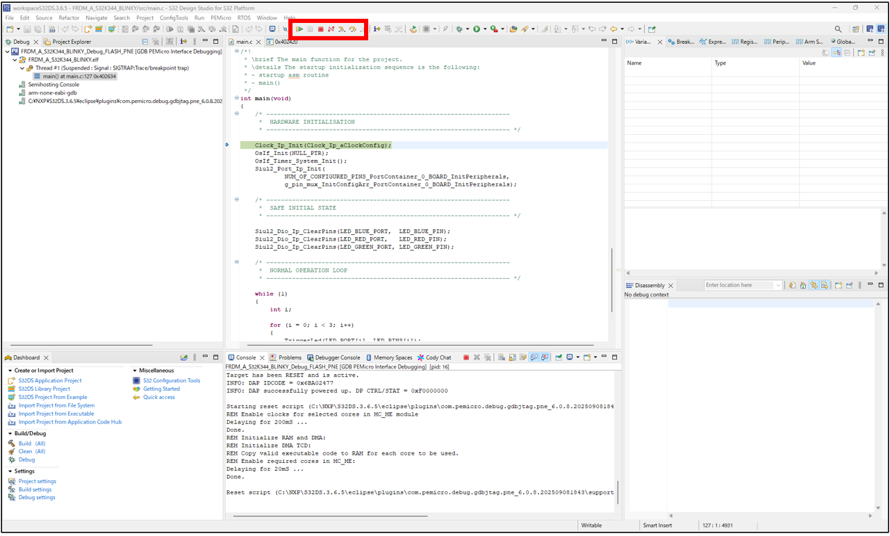
Figure 45 DEBUG window
In this example, the RGB LEDs on the development board light up in the order of blue → green → red, while repeatedly switching the LEDs on and off.
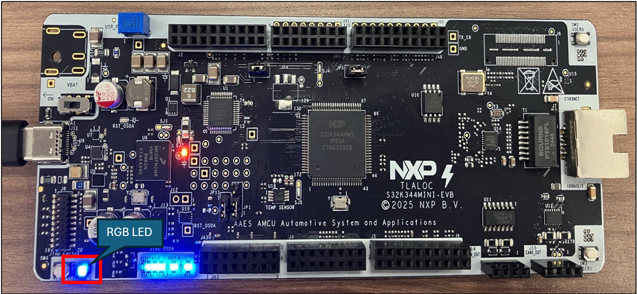
Figure 46 Development board (when blue light is on)
Summary
By using FRDM Automotive's software bundle, you can efficiently obtain and install a complete development environment including S32 Design Studio and RTD.
This book's instructions will allow you to follow the entire process, from installing the development environment to connecting the development board and verifying the operation of the sample application.
If you are interested in this information, please feel free to Inquiry Nexty Electronics.
Related Info
Inquiry
Related Product Information
Startup Guide: Trying out the FRDM-A-S32K312
This guide provides a clear explanation of everything from setting up the development environment for the NXP FRDM-A-S32K312 to building and debugging sample code.
- NXP Semiconductors NV
- NEXT Mobility
Overview of FRDM Automotive's evaluation board for automotive microcontrollers.
Introducing NXP's FRDM Automotive automotive, MCU evaluation board. Compatible with S32K/S32M, it efficiently supports everything from evaluation to prototyping and mass production development.
- NXP Semiconductors NV
- NEXT Mobility
Introducing NXP's Recommended Analog IC Products: The "Unseen Mainstays" Supporting ECU Development
This section showcases NXP's analog IC products for automotive ECUs, highlighting their role as components supporting peripheral functions such as sensors, RTCs, displays, communications, and POWER SUPPLIES.
- NXP Semiconductors NV
- NEXT Mobility

Introducing NXP's CAN TRANSCEIVER products with signal improvement (SIC)
NXP's SIC-equipped CAN TRANSCEIVER actively suppresses ringing on the transmitting side, stabilizing high-speed CANFD communications. It is software and pin compatible, allowing it to be replaced with existing designs, and is compliant with automotive standards.
- NXP Semiconductors NV
- NEXT Mobility

Introducing NXP's automotive LED DRIVER
Introducing NXP's automotive LED DRIVER. This product line supports constant voltage, constant current, high-precision PWM, and I2C/SPI, making it ideal for dimming multiple LEDs and displays.
- NXP Semiconductors NV
- NEXT Mobility

A thorough explanation of the appeal of NXP's automotive PMICs (Page 2/2) | An explanation of NXP's automotive PMIC portfolio and the features of its representative products.
This article explains the necessity of PMICs in automotive ECUs, as well as the features, advantages, and portfolio of NXP's automotive PMICs. This first part focuses on the automotive PMIC portfolio and the characteristics of its representative products.
- NXP Semiconductors NV
- NEXT Mobility
Link to Related Technical Columns
No need for an oscilloscope! High-precision time measurement using ARM-Cortex M DWT CYCCNT - A practical guide to minimized steps
This article provides an easy-to-understand explanation of the procedures and practical points for highly accurate time measurement on ARM Cortex-M using DWT CYCCNT without the need for external equipment.

Real-time AI tracking camera built with i.MX 93 - Achieving human tracking with NPU and servo motors
This document explains the procedure for building a camera that uses the i.MX 93 NPU and eIQ to perform face detection and track people in real time, from building a Yocto BSP to configuring PWM and using servo control.

A thorough explanation of the directories generated by bitbake | Essential for troubleshooting Yocto development
We will explain the structure and use of bitbake's tmp subdirectories (work, work-shared, deploy, etc.), as well as Yocto troubleshooting procedures using log checking and deb distribution.

Azure RTOS ThreadX Practical Guide: Practical Explanation of Task Management and Communication Functions
We will explain multitasking design and communication functions such as message queues in Azure RTOS (ThreadX).
First Steps with Azure RTOS: Creating a "Hello World" Project Using Azure RTOS
This article explains how to create, build, and debug a Hello World message using Azure RTOS (ThreadX) on the i.MX RT1170 evaluation board.

Building an i.MX Development Environment (Yocto Edition) | Technical Column
This article explains how to set up a Yocto development environment using NXP’s i.MX series. It covers hardware, preparation steps, and build procedures, helping you prepare to flash images on i.MX evaluation boards.