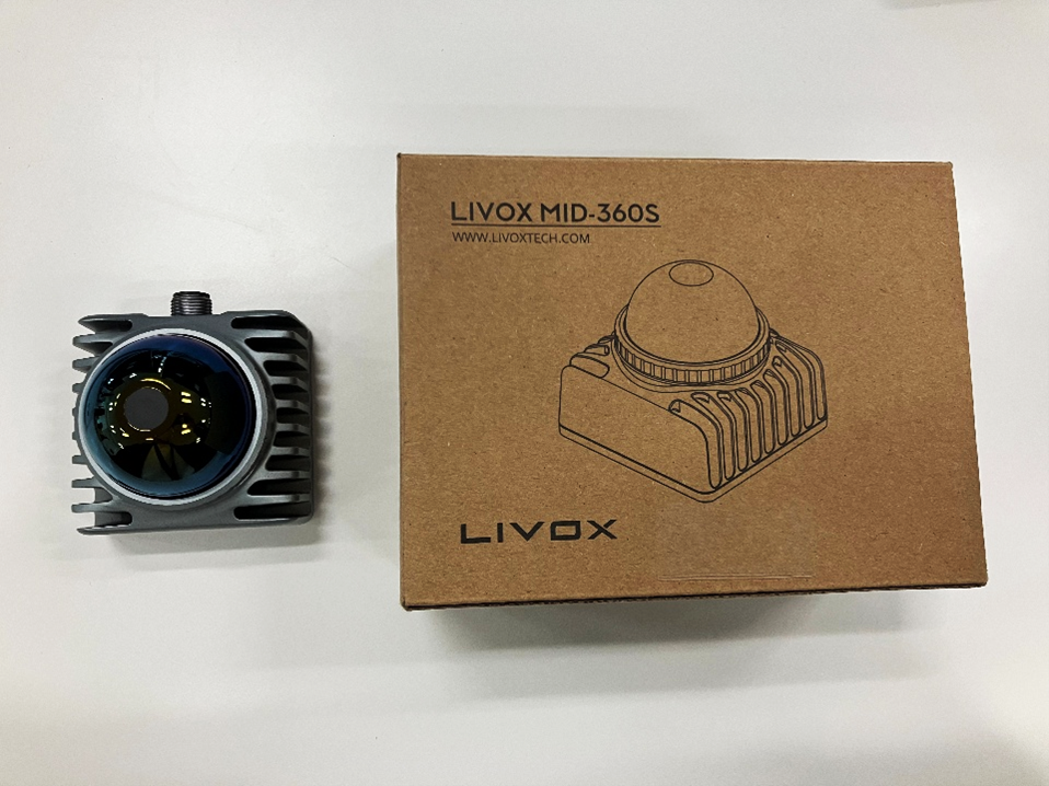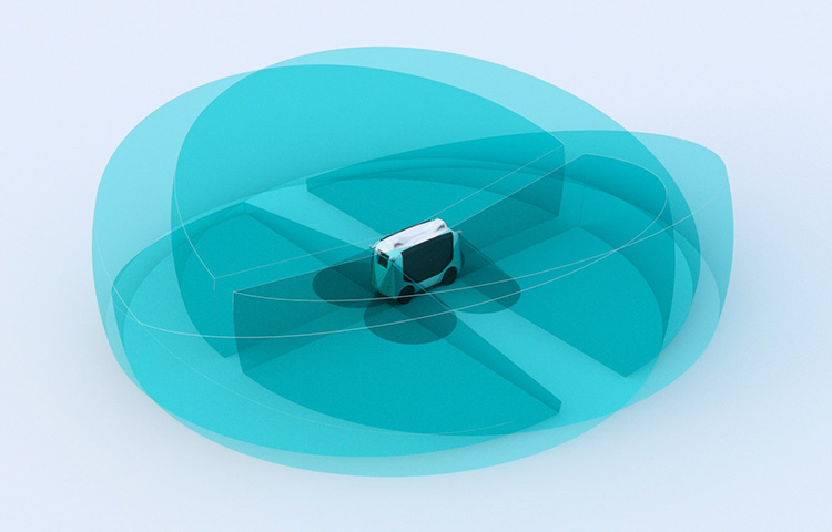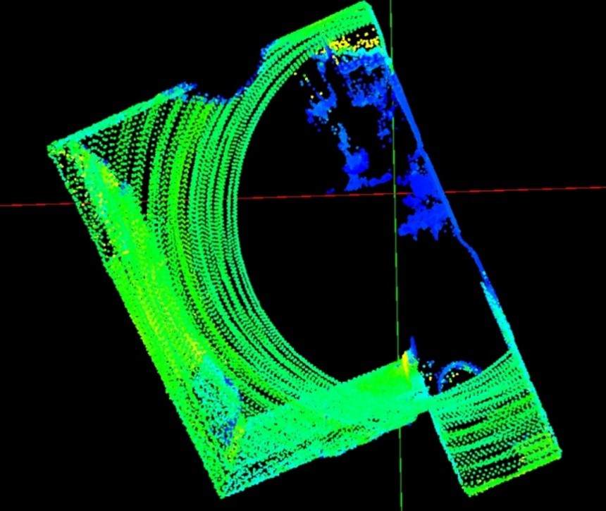
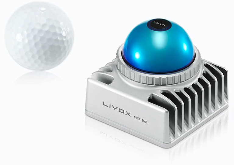
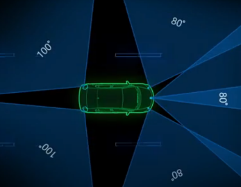
In recent years, the use of 3D LiDAR has rapidly expanded in the fields of AGV/AMR (autonomous mobile robots), infrastructure inspection, and security. Livox's MID-360 is a compact 3D LiDAR that features a wide 360° x 59° field of view and high-density point cloud output.
When incorporating the MID-360 into mass-produced products, the original CABLES designed for evaluation purposes may present constraints in terms of specifications and cost. It is important to consider designing your own CABLES at an early stage.
This article explains the fundamentals of CONNECTORS specifications and wiring design, which are the starting point for mass-production CABLES design, by demonstrating how to build an evaluation CABLES yourself.
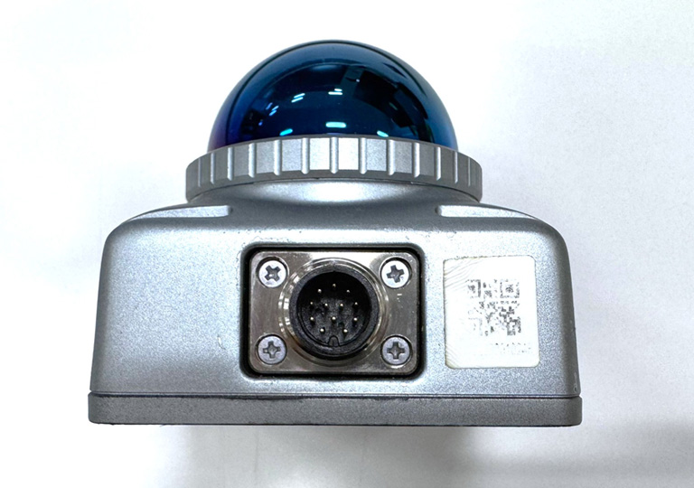
The MID-360 uses an industrial-grade M12 A-code 12 PIN CONNECTORS WITHOUT FRAME. This CONNECTORS conforms to IEC 61076-2-101, so it can be made in-house using compatible parts.
Choosing CONNECTORS connectors without understanding their specifications can lead to poor fit and malfunctions. Before proceeding to mass production design, it's effective to first grasp the basics of standards and wiring, and then test the sensor's operation with a custom-made CABLES.
In the sequel, "Practical Edition," we will introduce the actual CABLES production procedure and the results of our operational check.
MID-360 M12 CONNECTORS specifications
The MID-360 uses an M12 A-code 12 PIN CONNECTORS WITHOUT FRAME. The User Manual indicates compliance with the international standard IEC 61076-2-101. POWER SUPPLIES supply, Ethernet communication, and time synchronization signals can be connected together with a single CONNECTORS. Note that IEC 61076-2-101 specifies the physical shape and dimensions of CONNECTORS, and the signal assignment to each pin will vary from product to product.
Breakdown of 12 pins
The MID-360 features a 12-pin connector, integrating three functions—POWER SUPPLIES, communication, and synchronization—into a single CONNECTORS.
1. POWER SUPPLIES supply (4 pins): There are two Power+ (Pin 1/9) and two GND (Pin 2/3) pins, and they are wired in parallel to reduce voltage drop.
2. Ethernet communication (4 pins): Pins 4-7 are used for sending and receiving 100BASE-TX Ethernet.
3. Time synchronization (2 pins + 2 reserved pins): Time synchronization with an external system is possible using pin 8 (PPS input) and pin 10 (GPS input).
Pins 11/12 are spare LVTTL output IOs and will not be used for this synchronous connection.
INFO
For evaluation purposes, it will work if you wire the 8 pins for POWER SUPPLIES (Pin 1/2/3/9) and Ethernet (Pin 4/5/6/7).
If you do not use the time synchronization function, it is okay to leave pins 8/10/11/12 unconnected.
PIN ASSIGNMENT
The pin assignments for the MID-360 are shown below.
| Pin Number | Signal Name | type | Explanation |
|---|---|---|---|
| 1 | Power+ | POWER SUPPLIES | DC 9-27V |
| 2 | Ground | POWER SUPPLIES | GND |
| 3 | Ground | POWER SUPPLIES | GND |
| 4 | ETH_TX+ | Ethernet | Send+ |
| 5 | ETH_TX - | Ethernet | send- |
| 6 | ETH_RX+ | Ethernet | Receive+ |
| 7 | ETH_RX- | Ethernet | Receive- |
| 8 | LVTTL_IN | Signal | PPS Input |
| 9 | Power+ | POWER SUPPLIES | DC 9-27V |
| 10 | LVTTL_IN | Signal | GPS input |
| 11 | LVTTL_OUT | Signal | Reserved Output IO |
| 12 | LVTTL_OUT | Signal | Reserved Output IO |
*The wire colors of CABLES vary depending on CONNECTORS product.
M12 CONNECTORS standard IEC 61076-2-101
The MID-360 uses an M12 CONNECTORS compliant with IEC 61076-2-101. As long as the component complies with this standard, you can select compatible parts other than Livox-recommended CABLES.
M12 CONNECTORS standard
IEC 61076-2-101 is an international standard that defines the dimensions, electrical characteristics, and mechanical properties of industrial CIRCULAR CONNECTORS (M12). The standard specifies multiple coding options, pin counts, and genders. Connectors from different manufacturers can be mated (connected) if they share the same combination.
Coding (key layout)
M12 CONNECTORS have multiple "codings," which are used depending on the application. Coding is a system that defines the arrangement of CONNECTORS 's keys (protrusions) according to the standard, ensuring that CONNECTORS intended for different purposes do not physically interlock.
| coding | Main uses | Number of pins | shape |
|---|---|---|---|
| A Code | Sensors, ACTUATORS, POWER SUPPLIES | 3, 4, 5, 8, 12 pin | 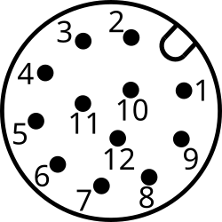 |
| B chord | Fieldbus (PROFIBUS, etc.) | 5-pin | 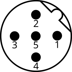 |
| D Code | 100Mbps Ethernet | 4-pin | 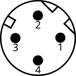 |
| X Code | Gigabit / 10Gbps Ethernet | 8-pin | 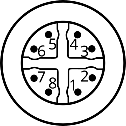 |
Image source: Wikimedia Commons
IEC 61076 M12 connector diagrams (CC BY‑SA 4.0)
The MID-360 uses an A-coded 12-pin cable. A-coded cables are widely used in industrial applications and are suitable for a wide range of applications, from POWER SUPPLIES supplies to Ethernet communications.
Differences in specifications and mounting configurations
The specification "A-code, 12-pin, female" specifies electrical compatibility (coding, pin arrangement, and mating part dimensions). IEC 61076-2-101 defines these electrical specifications and the mechanical dimensions of the mating part, but it does not specify CONNECTORS housing shape or mounting method. Therefore, even with the same "A-code, 12-pin, female" specification, products with different mounting configurations exist.
- CABLES plug: A structure that fastens to the mating CONNECTORS with a rotating nut (coupling nut).
- Panel mount receptacle: A structure that is fixed to the housing or panel with a flange or nut
The terms "one-sided assembled" and "pigtail" also indicate that CONNECTORS is already attached to the end of CABLES, and do not specify the type of CONNECTORS (plug or receptacle).
Key points for selecting parts
For the MID-360, please select CONNECTORS that meets the following four conditions.
1. Coding: A code (other codes cannot be physically connected)
2. Number of pins: 12
3. Gender: Female (because the MID-360 itself is male)
4. Mounting type: CABLES plug (structure with rotating nut. Check the product photo or outline drawing)
M12 CONNECTORS that meet these requirements are supplied by several manufacturers, including Amphenol, Phoenix Contact, and Harting.
When you search for electrical specifications on e-commerce sites like DigiKey or Mouser, the search results may include both CABLES plugs and panel mount receptacles.
This is because, if the electrical characteristics are the same, differences in mounting configuration are not reflected in the search criteria.
The easiest way to check for the presence or absence of a rotating nut is to look at the product photos, but if you are unsure, we recommend referring to the outline drawing in the datasheet.
Choosing a pigtail-type connector eliminates the need for soldering and crimping, thus reducing the difficulty of manufacturing.
WARNING
Panel-mount receptacles cannot be used to connect to the MID-360. Even if they meet the "A-code, 12-pin, female" requirements, panel-mount types without a rotating nut cannot be fastened to CONNECTORS on the MID-360 unit. Always select a CABLES plug.
-
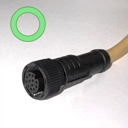
CABLES Plug
-
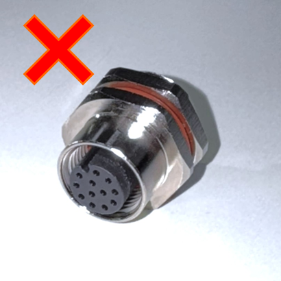
Panel mount receptacle
WARNING
Even for products that comply with the standards, the electrical characteristics (rated current, rated voltage, environmental resistance, etc.) vary depending on the manufacturer and product. Please check the datasheet according to your usage environment.
POWER SUPPLIES wiring design for DIY CABLES
We will explain the important points to consider when designing POWER SUPPLIES wiring for the MID-360.
POWER SUPPLIES Specifications
The POWER SUPPLIES specifications for the MID-360 are as follows:
| Item | Specifications |
|---|---|
| Operating Voltage Range | DC 9V - 27V |
| Recommended Voltage | 12V |
| Typical power consumption | 6.5W |
| Start-up peak power | 18W max. (below 35°C, for approx. 8 seconds) |
| Self-heating at low temperatures | 14W (-20°C to 0°C, max. 10 min) |
*All values are listed in the User Manual v1.2. Measurement conditions for normal power consumption (typ./max., etc.) are not specified. When designing wiring, ensure a safety margin based on peak power.
What does parallel wiring mean?
On the MID-360 CONNECTORS, Power+ is assigned to pins 1 and 9, and GND is assigned to pins 2 and 3. Livox's technical information states that parallel wiring of these pins is mandatory.
The per-pin current rating of an M12 CONNECTORS is typically around 1.5A to 2A for a standard A-code 12-pin product. However, the MID-360's peak startup current reaches a maximum of 1.5A when powered at 12V. By using two connectors in parallel, the current per pin is reduced to approximately 0.75A, avoiding the risk of exceeding the rating of a single pin.
INFO
According to Livox's official policy, Power+ and GND must be wired in parallel, regardless of the rated current or peak conditions at startup.
CABLES Length and Voltage Drop
The table below shows an example of calculating the voltage drop when AWG26 (0.14 mm²) CABLES are wired in parallel and a 12 V power supply is applied. AWG26 is a common wire diameter for single-end pre-assembled M12 CABLES. Using a thicker wire diameter such as AWG24 (0.25 mm²) can further reduce the voltage drop.
Furthermore, when using a 24VDC POWER SUPPLIES, which is widely used in industrial equipment, the impact on the sensor terminal voltage is smaller even with the same voltage drop, allowing for greater leeway when using long CABLES.
| CABLE length | Operation Mode | current | Voltage drop | Sensor terminal voltage |
|---|---|---|---|---|
| 1m | usually | 0.54A | 0.07V | 11.93V |
| 1m | Start-up Peak | 1.50A | 0.20V | 11.80V |
| 3m | usually | 0.54A | 0.22V | 11.78V |
| 3m | Start-up Peak | 1.50A | 0.60V | 11.40V |
| 5m | usually | 0.54A | 0.36V | 11.64V |
| 5m | Start-up Peak | 1.50A | 1.01V | 10.99V |
calculation formula
Voltage drop = 2 × CABLES length (m) × resistivity (Ω/m) × current (A) ÷ 2 (parallel)
- AWG26 resistivity: Approximately 0.134 Ω/m (at 20°C, with an error of approximately ±10%)
- The factor "2" is for the round trip (Power+ and GND), and is finally divided by 2 due to parallel wiring.
- Example: 3m, 1.50A → 2 × 3 × 0.134 × 1.50 ÷ 2 ≒ 0.60V
WARNING
There is a risk that the voltage at the sensor end will fall below the lower operating limit (9V) due to voltage drop in CABLES.
A 12V power supply is an easy design condition to handle, as it is easy to ensure a voltage drop margin.
INFO
If you are using a long CABLES (over 3m), consider increasing POWER SUPPLIES voltage to around 12V to 13V.
However, care must be taken not to exceed the maximum voltage of 27V.
Ethernet cabling design points
The MID-360 communicates via 100BASE-TX Ethernet. We will explain the key points of wiring design.
Communication specifications
| Item | Specifications |
|---|---|
| Communication Standards | 100BASE-TX (IEEE 802.3u) |
| Communication speed | 100Mbps |
| Protocol | UDP |
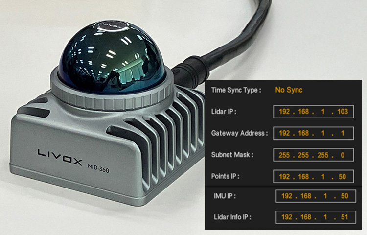
| IP Settings | Static IP (default: 192.168.1.1XX) |
| Subnet mask | 255.255.255.0 |
100BASE-TX uses a differential transmission method, using two pairs of signal wires: TX+/TX- (transmit) and RX+/RX- (receive), for a total of four. Differential transmission is resistant to external noise. Even if both pairs of signal wires are subjected to the same noise, the noise components are canceled out by taking the difference.
Signal pin correspondence
The correspondence between the Ethernet signal pins of the MID-360 and the RJ45 CONNECTORS (T568B wiring) is as follows:
| MID-360 pin | Signal | RJ45 pin (T568B) |
|---|---|---|
| Pin4 | TX+ | Pin1 |
| Pin5 | TX- | Pin2 |
| Pin6 | RX+ | Pin3 |
| Pin7 | RX- | Pin6 |
Need for a shield?
The MID-360 user manual does not specify requirements for shielding. Finecables CABLES are recommended, but the need for shielding should be evaluated based on the usage environment. 100BASE-TX Ethernet uses a differential transmission method and is resistant to common-mode noise.
If the following conditions are met, it may be possible to check operation even with an unshielded CABLES for evaluation purposes where the conditions are limited.
- For short distance use: Recommended CABLES length is about 1.5 m, but even if extended, it should be no longer than 10 m.
- Low-noise environment: No strong electromagnetic noise sources (large motors, INVERTERS, etc.) nearby
- Evaluation and verification purposes: The main purpose is to check operation, not to incorporate into a full-scale product.
However, if the environment is close to a strong electromagnetic noise source or if long-distance wiring is required, we recommend a separate on-site evaluation.
WARNING
The MID-360 does not support PoE (Power over Ethernet). Do not connect it to a PoE SWITCHES or PoE injector by mistake, as this may cause damage to the device.
Summary
This column explained CONNECTORS specifications and wiring design points for the Livox MID-360.
Key points of CONNECTORS specifications
- The MID-360 uses an M12 A-code 12-pin CONNECTORS compliant with IEC 61076-2-101.
- If they comply with the standards, CONNECTORS from different manufacturers can be physically mated together.
- The IEC standard specifies coding, pin arrangement, and electrical characteristics, but does not specify mounting configuration.
- A CABLES plug with a rotating nut is required to connect to the MID-360 (check the product photo or outline drawing).
- For evaluation purposes, it operates with a total of 8 pins: 4 pins POWER SUPPLIES and 4 pins for Ethernet.
POWER SUPPLIES supply wiring points
- Voltage: 12V recommended (9V power supply may cause voltage drop)
- Parallel wiring (required): Connect two Power+ (Pin 1/9) and two GND (Pin 2/3) in parallel.
- Longer CABLES: Increase voltage (up to 27V) for lengths over 3m
Ethernet wiring tips
- Differential pairs: TX+/TX-, RX+/RX- pairs must be routed correctly
- Shielding: Not considered necessary in short distances and low noise environments
- PoE not supported: Be careful not to connect to PoE devices incorrectly
In the next "Practical Application" session, we will actually fabricate CABLES using Amphenol MSAP-12BFFM-SL8A01 (one-sided pre-assembled M12 CONNECTORS) and verify its connection and operation with the MID-360.
![Making your own CABLES for the Livox MID-360 [Practical Guide]](/uploads/media_files/livox_10_thumbnail-3954867486.jpg)