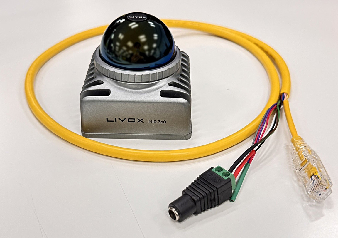
In the previous "Understanding the Specifications" section, we explained the specifications of the Livox MID-360's M12 CONNECTORS (A code 12 pins, compliant with IEC 61076-2-101) and key points for wiring design. In this column, we will actually make an M12 CABLES ourselves and verify its connection and operation with the MID-360. The Amphenol MSAP-12BFFM-SL8A01 used this time has the M12 CONNECTORS side pre-assembled. The other side is wired out, so it can be completed by simply crimping the RJ45 CONNECTORS and paralleling POWER SUPPLIES wires. No crimping or soldering to the M12 CONNECTORS is required. However, wiring mistakes can lead to equipment damage, so this column will explain the signal mapping and continuity verification procedures in detail.
I actually fabricated CABLES using this method and successfully acquired point cloud data with Livox Viewer 2. This method is perfectly practical for evaluation and verification purposes.
Preparation of materials
Prepare the materials needed to make your own CABLES. I will introduce the materials I used and the reasons for my selection.
Selection of CONNECTORS to be used
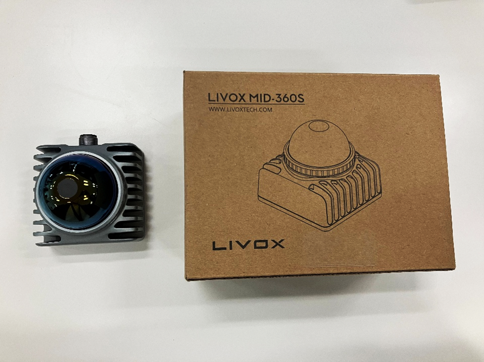
This time, I used the MSAP-12BFFM-SL8A01 from Amphenol LTW. It's an M12 A-code 12 PIN CONNECTORS WITHOUT FRAME compliant with IEC 61076-2-101, available from electronic component online retailers such as DigiKey and Marutsu Online.
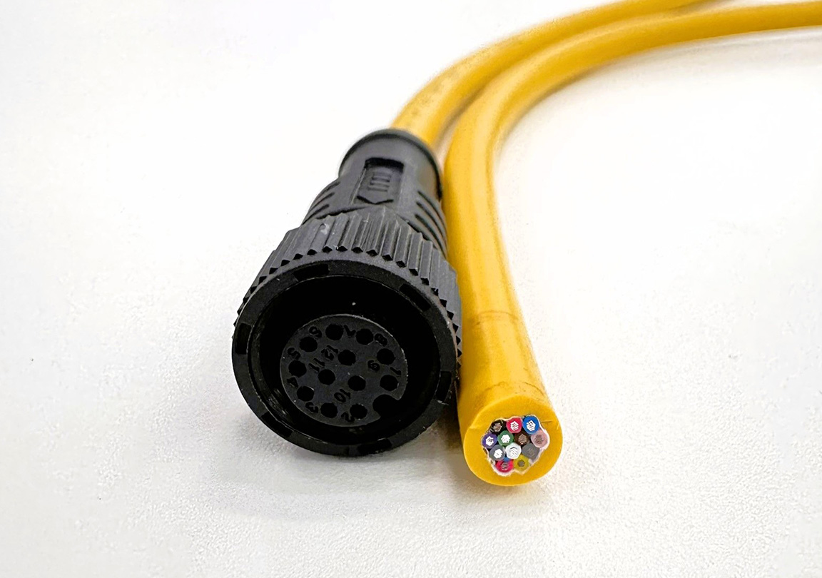
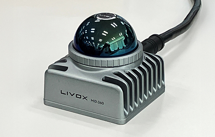
Appearance of MSAP-12BFFM-SL8A01
| Item | Specifications |
|---|---|
| CONNECTORS shape | M12 A code 12 pin (female) |
| Form | One side is pre-assembled (M12 side is assembled, the other side has wires exposed). |
| Specifications | Compliant with IEC 61076-2-101 |
| CABLES compatible | AWG26 (0.14mm²) |
| Waterproof rating | IP68/69K (when mated)/69K (when mated)b |
| CABLE length | 1m |
| CABLE jacket | UL2517 PVC |
A key feature of this product is that the M12 CONNECTORS side is pre-assembled. The other side has CABLES already wired, so all you need to do is crimp an RJ45 CONNECTORS onto the Ethernet signal wires and connect POWER SUPPLIES wires in parallel to complete the assembly. Since crimping and soldering to CONNECTORS are not required, the difficulty of assembly is reduced.
Since the MID-360 unit has a male CONNECTORS, the connecting CABLES must have a female connector.
INFO
When selecting CONNECTORS, be sure to check these three points: the number of pins (12 pins), the coding (A code), and the gender (female). If these are different, the connectors will not be able to be physically mated.
Other necessary parts
The MSAP-12BFFM-SL8A01 comes pre-assembled on one side, so there is no need to cut CABLES wires separately.
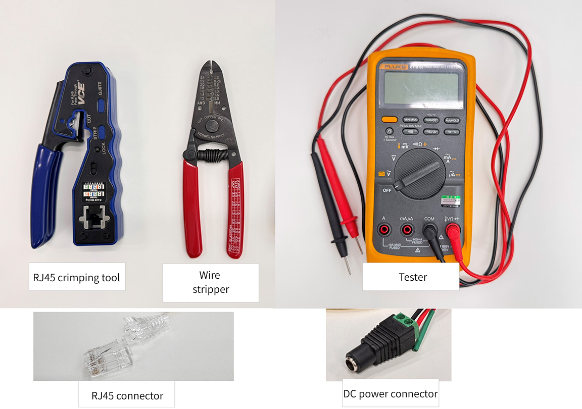
Required parts
| Components | Purpose | Remarks |
|---|---|---|
| RJ45 CONNECTORS | Ethernet connection | For PC connection |
| RJ45 crimping tool | CONNECTORS crimping | Common tools for creating LAN CABLES |
| DC POWER SUPPLIES CONNECTORS | POWER SUPPLIES connection | Select according to AC ADAPTERS you will be using. |
| Tester | Continuity check | For checking after wiring completion |
| Heat shrink tubing | Insulation and protection | For insulating parallel connections of POWER SUPPLIES lines. |
| Wire stripper | peeling | For POWER SUPPLIES Wire Processing |
CABLES manufacturing
Based on the signal mapping explained last time, we will now actually manufacture CABLES.
Signal Mapping Table
This shows PIN ASSIGNMENT for the MID-360 and their correspondence with the MSAP-12BFFM-SL8A01. For this example, we will only wire the 8 POWER SUPPLIES and Ethernet pins (pins 8/10/11/12 are left unconnected as the time synchronization function will not be used).
| MID-360 pin | Signal Name | MSAP line color | Connection destination |
|---|---|---|---|
| Pin1 | Power+ | White | POWER SUPPLIES + |
| Pin2 | Ground | Brown | POWER SUPPLIES- |
| Pin3 | Ground | Green | POWER SUPPLIES- (bundle with Pin 2) |
| Pin4 | ETH_TX+ | Yellow | RJ45 Pin1 |
| Pin5 | ETH_TX - | Gray | RJ45 Pin2 |
| Pin6 | ETH_RX+ | Pink | RJ45 Pin3 |
| Pin7 | ETH_RX- | Blue | RJ45 Pin6 |
| Pin8 | LVTTL_IN | Red | Not connected |
| Pin9 | Power+ | Black | POWER SUPPLIES + (bundle with Pin1) |
| Pin10 | LVTTL_OUT1 | Purple | Not connected |
| Pin11 | LVTTL_OUT2 | Gray/Pink | Not connected |
| Pin12 | GND_LVTTL | Red/Blue | Not connected |
Production procedure
Since the MSAP-12BFFM-SL8A01 comes with the M12 CONNECTORS already assembled, the manufacturing process can be reduced to the following two steps:
1. Crimping the RJ45 CONNECTORS to the Ethernet signal line.
2. POWER SUPPLIES line extraction and parallel connection
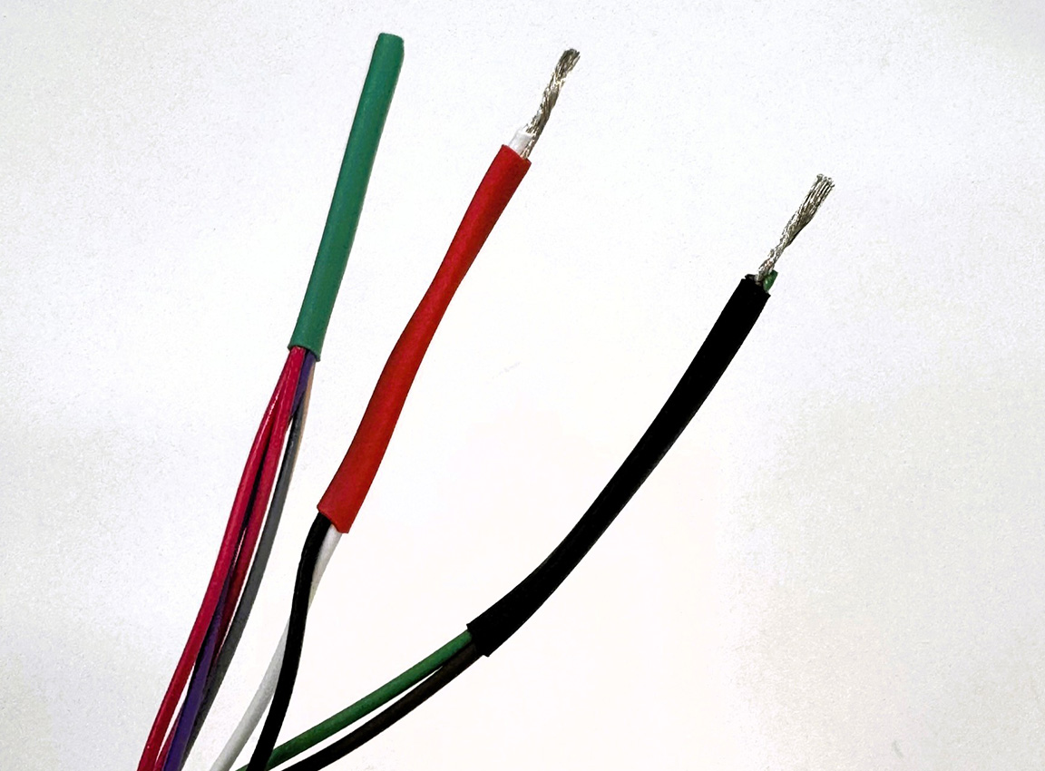
1. Check and disconnect CABLES
Separate the 12 wires coming from the MSAP-12BFFM-SL8A01 according to their intended use.
- POWER SUPPLIES wires: White (Pin1), Brown (Pin2), Green (Pin3), Black (Pin9)
- Ethernet cable: Yellow (Pin4), Gray (Pin5), Pink (Pin6), Blue (Pin7)
- Unused wires: Red (Pin8), Purple (Pin10), Gray/Pink (Pin11), Red/Blue (Pin12)
Cut any unused wires to the appropriate length and insulate them (using heat shrink tubing, etc.).
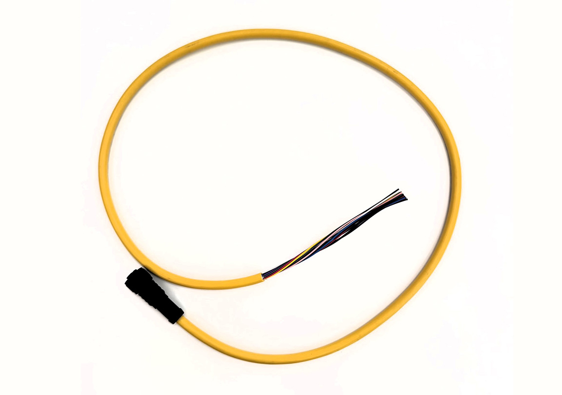
Extraction of wire
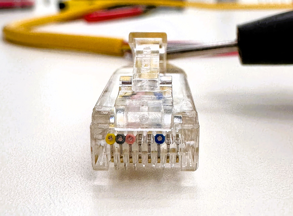
2. Crimping the RJ45 CONNECTORS
Crimp the four Ethernet signal wires to the RJ45 CONNECTORS using the following method.
| MSAP line color | Signal | RJ45 pin |
|---|---|---|
| Yellow (Pin4) | TX+ | Pin1 |
| Grey (Pin5) | TX- | Pin2 |
| Pink (Pin6) | RX+ | Pin3 |
| Blue (Pin7) | RX- | Pin6 |
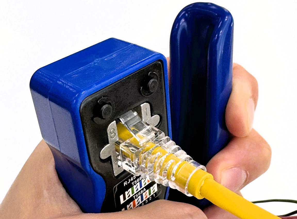
Crimping to RJ45 CONNECTORS
The remaining pins on the RJ45 CONNECTORS (Pin 4, 5, 7, 8) are unused and will be left empty.
Checking the RJ45 TERMINALS configuration
INFO
TERMINALS on an RJ45 CONNECTORS are numbered 1, 2, 3… from left to right when viewed from the front (with the CONNECTORS facing upwards). Please be sure to check this before crimping.
3. Parallel connection of POWER SUPPLIES lines
Connect POWER SUPPLIES lines in parallel, bundling the Power+ (white and black) and GND (brown and green) wires together.
- Connect the white (Pin1) and black (Pin9) Power+ wires together → to POWER SUPPLIES +.
- Bundle the brown (Pin2) and green (Pin3) GND wires → Connect to POWER SUPPLIES (-).
The bundled wires are connected by soldering or TERMINALS, and then insulated and protected with heat shrink tubing.
Parallel connection and insulation of POWER SUPPLIES lines
INFO
Parallel wiring of Power+ and GND is essential. Using a single pin will not provide the required current capacity, leading to voltage drop and overheating.
WARNING
The longer CABLES, the greater the voltage drop. With this CABLES (AWG26, 1m), the voltage drop is approximately 0.20V even at the peak current during startup. However, when extending or connecting cables, please refer to the voltage drop calculation in the "Understanding Specifications" section and ensure that the sensor terminal voltage does not fall below the operating lower limit (9V). A power supply voltage of 12V or higher is recommended.
4. Installing POWER SUPPLIES CONNECTORS
Attach POWER SUPPLIES CONNECTORS (DC JACKS, etc.) according to AC ADAPTERS you are using. Be careful not to get the polarity (+/-) wrong.
5. Continuity check
After the wiring is complete, use a tester to check for continuity and short circuits.
Continuity check: Verify that there is continuity from the pins on the M12 CONNECTORS to the corresponding end of CABLES.
| M12 pin | Signal | Where to check | Expected results |
|---|---|---|---|
| Pin1 (white) | Power+ | DC CONNECTORS + | Continuity present |
| Pin9 (Black) | Power+ | DC CONNECTORS + | Continuity is present (in parallel with Pin1). |
| Pin2 (brown) | GND | DC CONNECTORS- pin | Continuity present |
| Pin3 (Green) | GND | DC CONNECTORS- pin | Continuity is present (in parallel with Pin2). |
| Pin4 (yellow) | ETH_TX+ | RJ45 Pin1 | Continuity present |
| Pin5 (gray) | ETH_TX - | RJ45 Pin2 | Continuity present |
| Pin6 (Pink) | ETH_RX+ | RJ45 Pin3 | Continuity present |
| Pin7 (blue) | ETH_RX- | RJ45 Pin6 | Continuity present |
Short circuit check: Always ensure there is no continuity between Power+ (white/black) and GND (brown/green). Incorrect polarity connection can cause equipment damage.
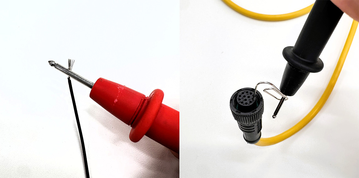
Verification by tester
6. Completion
The custom-made CABLES is now complete. CONNECTORS is already assembled, so no further assembly is required.
Completed self-made CABLES
Operation check: Connection to PC and point cloud acquisition.
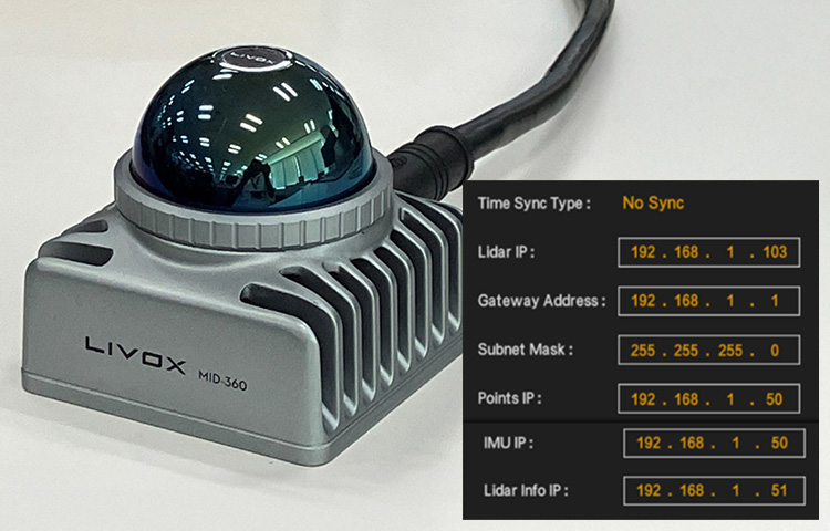
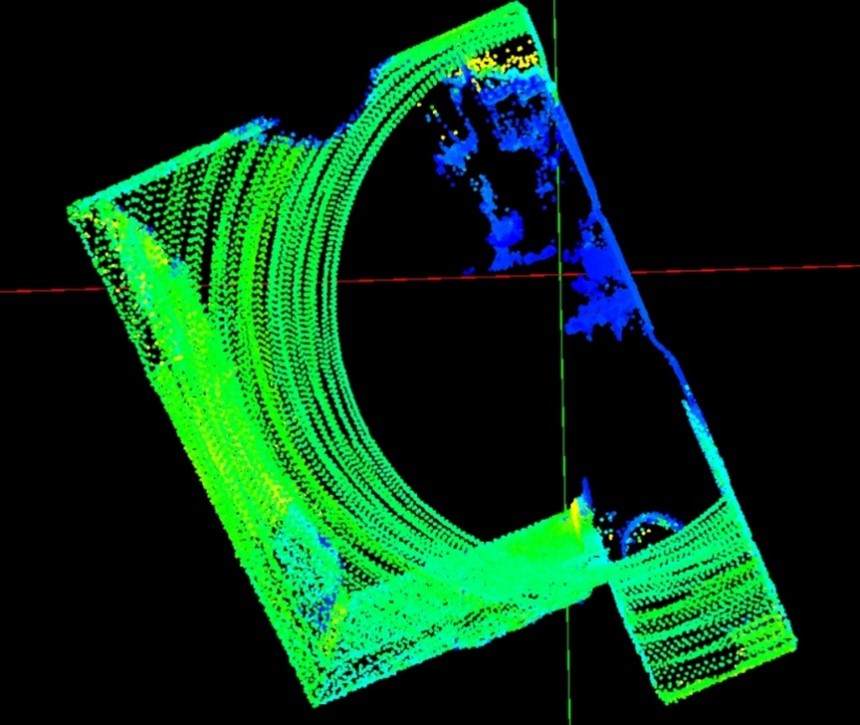
Using CABLES I fabricated, I successfully connected the MID-360 to a Windows PC and acquired point cloud data. Even a homemade CABLES is perfectly practical for evaluation and verification purposes.
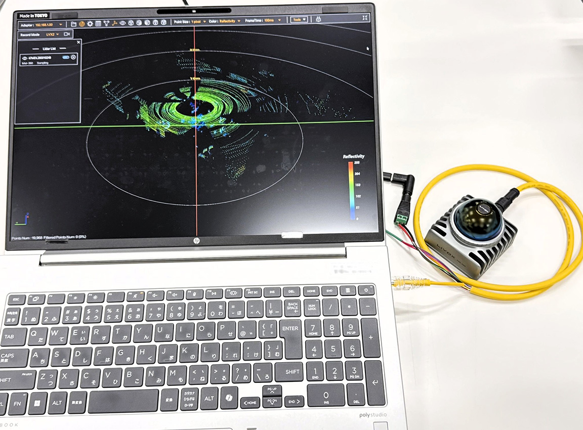
Testing the operation of the MID-360 using a custom-made CABLES.
INFO
For information on connection and operation verification, please see "Visualizing LiDAR Point Cloud Data! How to Use Livox Viewer 2".
Summary
This column explains how to make your own M12 CABLES for the Livox MID-360.
Key points of production
- Utilizing a single-sided assembly: The MSAP-12BFFM-SL8A01 has the M12 side already assembled, so it can be completed by simply crimping the RJ45 connector and paralleling POWER SUPPLIES wires.
- Check wire colors: Refer to the signal mapping table and wire using the correct wire colors.
- Continuity check: After wiring, always check for continuity and short circuits with a multimeter.
Practical for evaluation and verification purposes
I made my own CABLES using MSAP-12BFFM-SL8A01. I successfully acquired MID-360 point cloud data using a Windows 11 PC and Livox Viewer 2. This is a perfectly practical method for evaluation and verification purposes.
Please note that Livox's genuine CABLES are intended for evaluation purposes. For full-scale product integration or long-term operation, please consider a separate CABLES design tailored to your specific environment.
For details on CONNECTORS specifications and wiring design, please refer to the previous "Understanding Specifications" section.
Reference information
Product Information
Livox MID-360
- Product page
- User Manual: Livox Mid-360 User Manual v1.2
Livox Viewer 2
Amphenol MSAP-12BFFM-SL8A01
Standards and technical information
IEC 61076-2-101: International standard for industrial CIRCULAR CONNECTORS (M12)
Disclaimer
The content of this column is based on verification for demonstration and evaluation purposes. We cannot be held responsible for any equipment failure or damage caused by the use of self-made CABLES. For full-scale product integration or long-term operation, please consider separate CABLES designs that meet the operating environment and reliability requirements.
![Livox MID-360 M12 CABLES DIY [Understanding the Specifications]](/uploads/media_files/livox_10_thumbnail-3954867486.jpg)